
Technical Articles and Engineering News
Explore magnetic connector manufacturing, device-specific engineering and industry developments through the technical articles below.
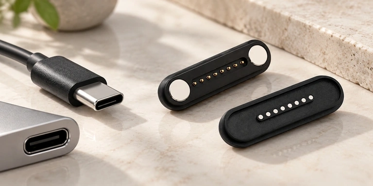
Eight-Contact Magnetic Mates and USB-C: OEM Interface Choices
Compare guided magnetic docking, designed breakaway and custom contact maps with USB-C's standard ecosystem and implemented protocols. Power, data, enclosure and mating requirements determine which architecture fits, or how the two may be combined.
Read Article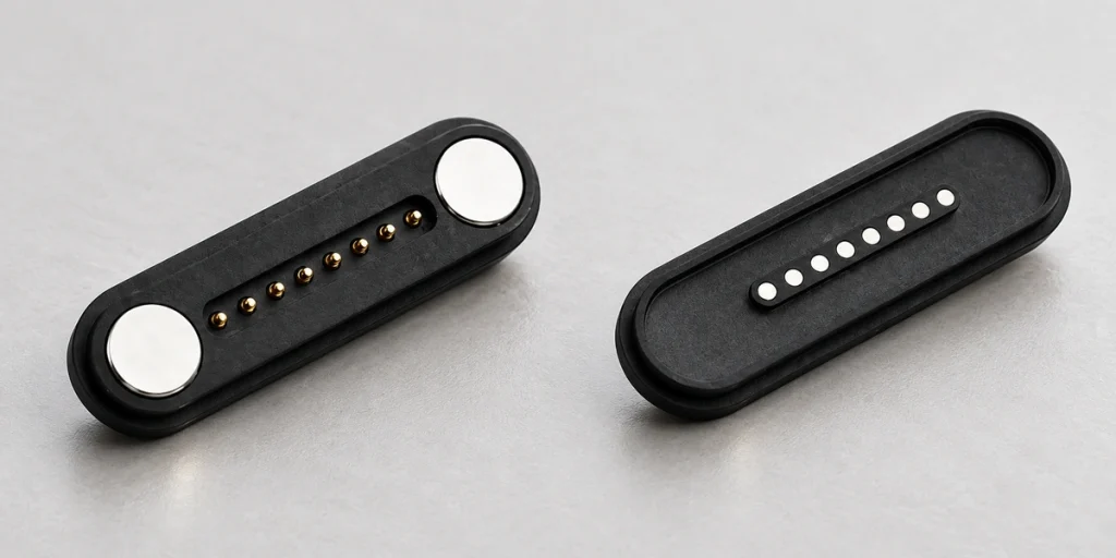
Eight-Contact Magnetic Interfaces for Power and Data
An eight-contact interface may carry power and data together when contacts, cable, PCB and assignments meet the required current and signal conditions. Allocate power, return, data, ID, detection and controls from the device circuit, then validate the complete path.
Read Article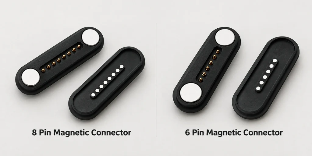
Six or Eight Magnetic Contacts: Circuit and PCB Selection
Six positions may cover power, ground, data and basic ID; eight add two possible signal, detection or control paths. Choose using assignments, current, PCB space, dimensions and actual device functions rather than assuming that more contacts improve performance.
Read Article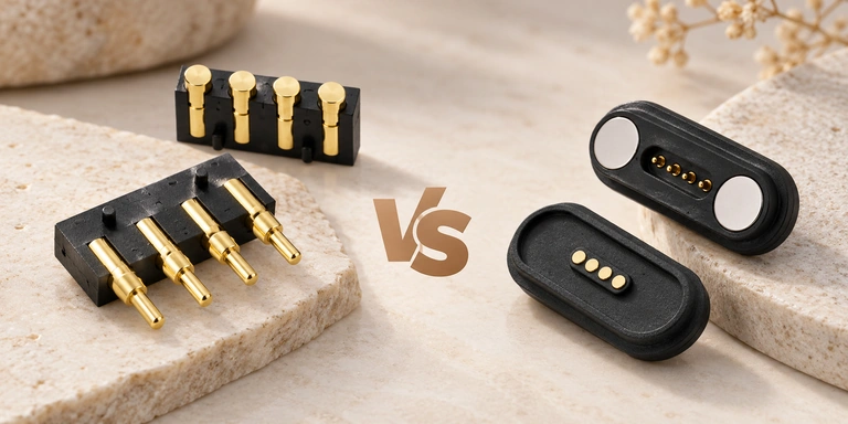
Four-Contact Magnetic and Pogo Interfaces: How to Choose
Both assemblies may use spring-loaded contacts for power or signals. The magnetic version adds a guidance and retention system. Compare alignment, retention, mating behavior and the complete device requirements when selecting a four-contact interface.
Read Article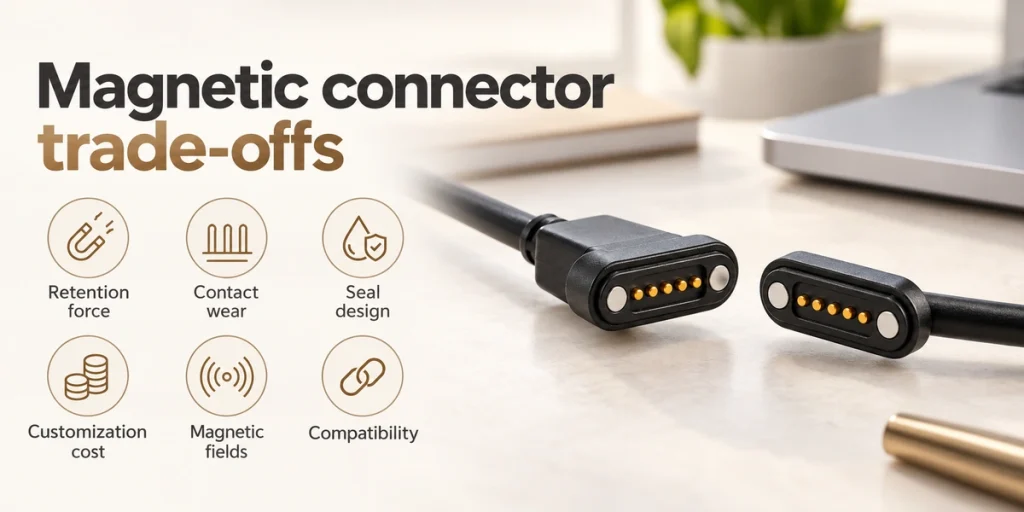
Magnetic Connector Limitations: Six OEM Design Trade-Offs
Guided detachable mating still needs evaluation for holding force, pogo-contact wear, sealing, customization cost, magnetic-field effects and compatibility. Retention in particular must meet the actual loads, and the other limits must be reviewed against the application.
Read Article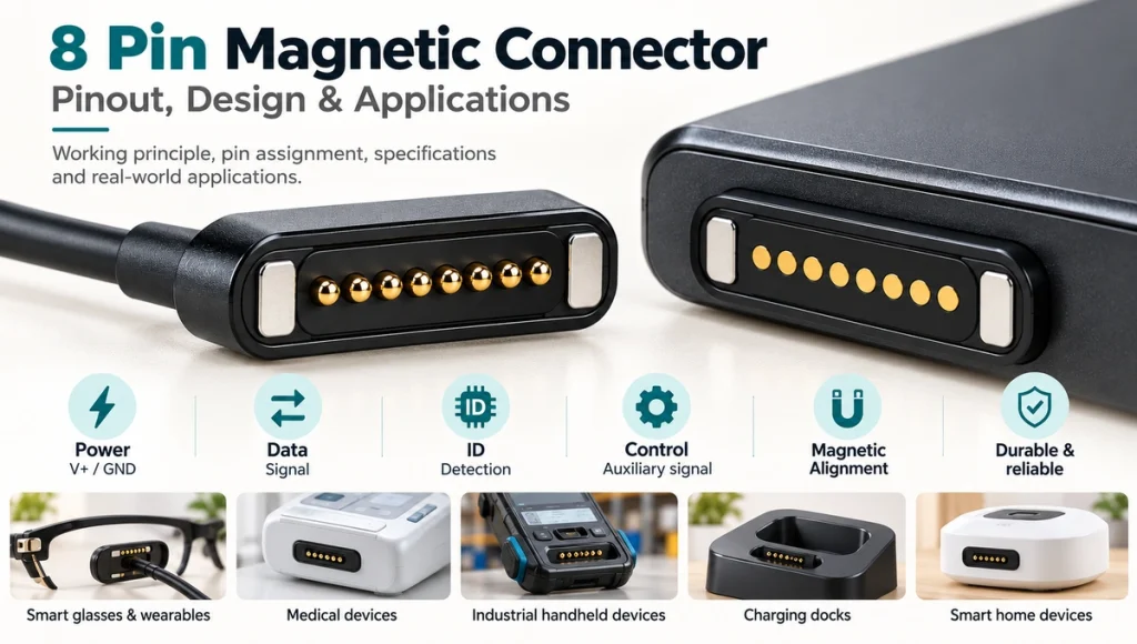
Eight-Contact Magnetic Connectors: Pin Maps and OEM Design
Eight conductive contacts with magnetic guidance can allocate power, ground, data, ID and controls within a compact detachable OEM mate. Define the device-specific map and architecture; physical count supplies neither universal functions nor an electrical rating.
Read Article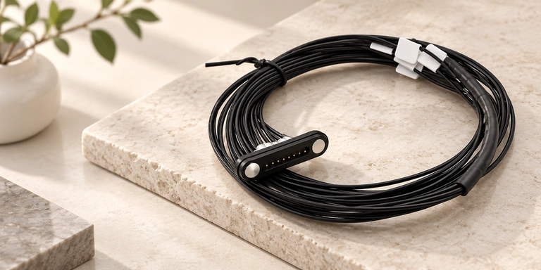
8-Pin Magnetic Cable Connectors: From Circuit Paths to OEM Integration
An eight-contact magnetic cable may allocate power, signals, ID, detection and controls. With no universal map, specify current, cable type, magnetic force and device integration for the application before selecting the assembly.
Read Article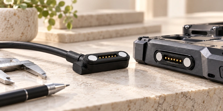
6-Pin Magnetic Charging Cables: An OEM Interface Design Guide
Six positions may combine power, data, ID, detection or controls. Begin with the actual functions, then define the map, current, cable end, magnetic mating and reliability requirements before OEM prototype development.
Read Article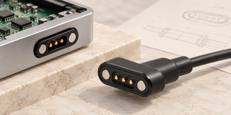
3-Pin Magnetic Charging Cables: Pin Functions, Compatibility and OEM Design
Three contacts may provide charging plus ID, detection, control or another signal. Review the actual map, data path, compatibility, specifications and OEM requirements; magnetic guidance and contact count alone do not define the extra function.
Read Article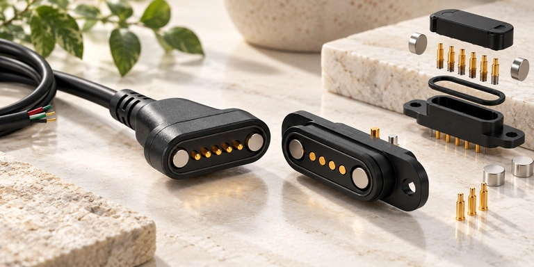
Designing a Custom Magnetic Connector Around the Device
Start custom design with electrical, mechanical and environmental requirements. Coordinate the map, working stroke, spring and magnetic forces, alignment, sealing, cable or PCB integration and prototype validation around the device.
Read Article