
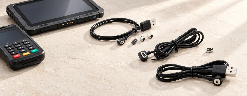
2-Pin Magnetic Charging Cables Built to Fit
For an OEM device, specify a magnetic charging cable with two electrical contacts. Cable length, electrical polarity, magnetic head dimensions and wire gauge are defined around the project constraints.
Available in USB-A, USB-C, or open-wire options
Customizable polarity, dimensions & wire gauge
17 Years of Factory Manufacturing & Precision Design
Common Types of 2 Pin Magnetic Charging Cables
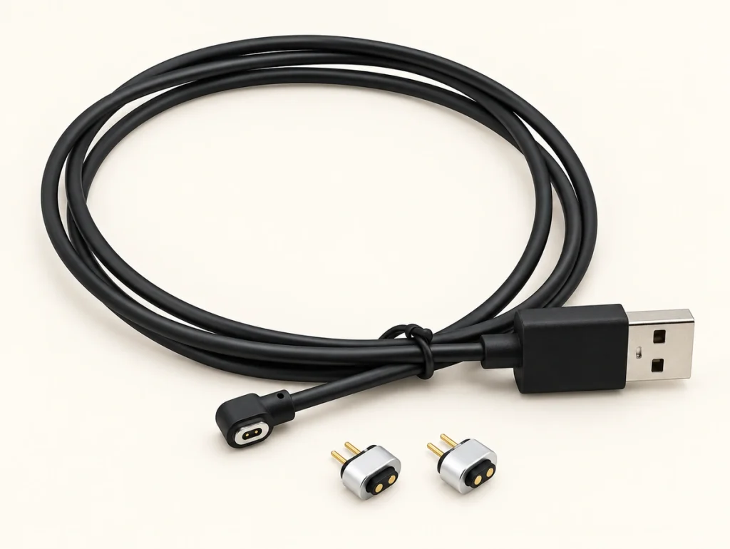
2 Pin Magnetic Charging Cable
Current Rating 2A
Pitch 1.50mm
Durability 10,000+ Cycles
End Type USB-A / USB-C /Bare Wire
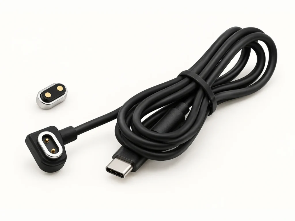
2 Pin Magnetic Cable Connector
Current Rating 1A
Pitch 3.25mm
Durability 10,000+ Cycles
End Type USB-A / USB-C /Bare Wire
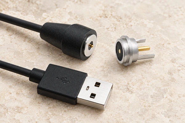
Circular Magnetic Cable Connector
Current Rating 2A
Diameter 8.50mm
Waterproof IP67
End Type USB-A / USB-C /Bare Wire
Charging Current and Cable End Options
Two contacts provide a power path, but they do not establish fast-charging capability. Charging performance depends on contact ratings, resistance, wire gauge, cable length and the charging circuit inside the device.
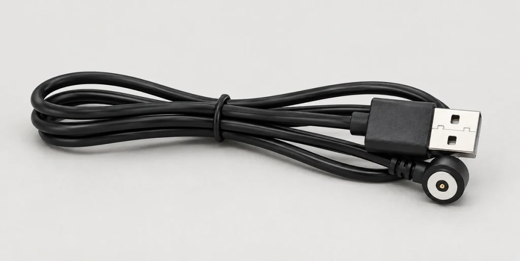
USB-A Interface
A common choice for standard USB power sources and charging docks.
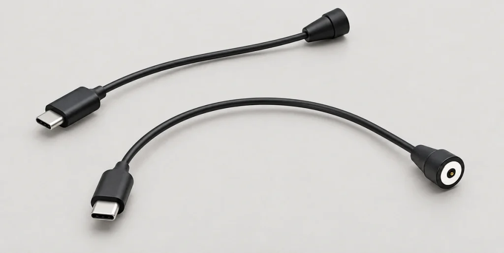
USB-C Interface
USB-C can be the power-source end for a modern device. That connector alone does not enable USB PD or a fast-charging protocol across the two-contact interface.
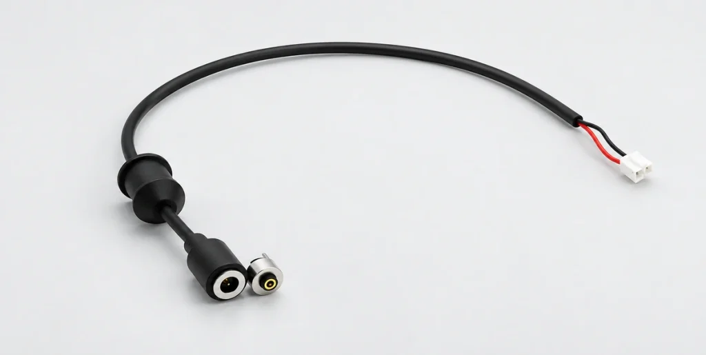
Open Wire / Terminal
Open leads or terminals suit internal harnesses, custom charging docks and industrial integration.
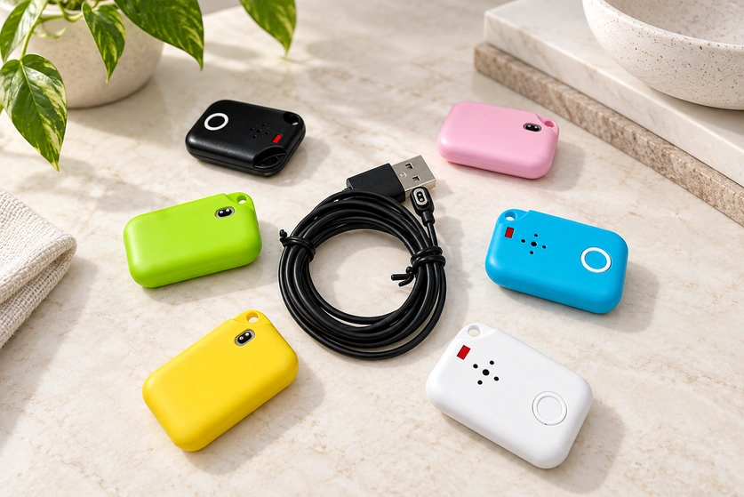
What Is a 2 Pin Magnetic Charging Cable?
Two electrical contacts, normally assigned to positive and negative DC power, form the charging path. In the described design, N52 magnets guide the cable toward the device-side interface and spring-loaded pogo pins complete the electrical contact.
The term two-pin describes contact count, not universal compatibility. The magnetic cable must match the physical and electrical specifications of the device-side connector; two chargers with two contacts are not necessarily interchangeable.
How Do I Know If a 2 Pin Magnetic Charger Is Compatible?
Check compatibility before choosing a replacement cable or a connector for a new device. A two-contact magnetic interface is generally project-specific.
Compatibility Checklist
Pitch and dimensions: match the contact center distance and ensure the housing fits the device opening.
Magnetic and electrical polarity: the magnets must attract, and VCC and GND must meet their corresponding contacts. Validate polarity to address short-circuit risks.
Voltage and current: select conductor size and pogo pin ratings to support the device charging requirements.
Working height: provide enough pin travel and compression to maintain pressure on the device pads.
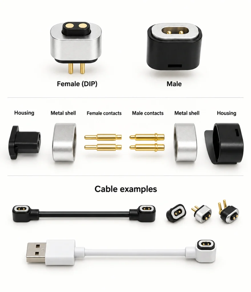
Circular 2 Pin Magnetic Charging Cable
A circular head can suit a compact recessed port or an interface that needs environmental protection. A concentric contact design may allow rotation-independent alignment; other round arrangements need keying to maintain electrical polarity.
A round format can save space in wearables, outdoor electronics and portable devices where a rectangular head would be difficult to install.
Reference Specification: Circular Magnetic Cable
Round magnetic structure
DC 12V / 2A Max
USB-A / USB-C /Bare Wire
IP67 Waterproof Rating
10,000 mating cycles min.
48H salt spray tested
Custom magnetic cable specifications can be reviewed for the project.
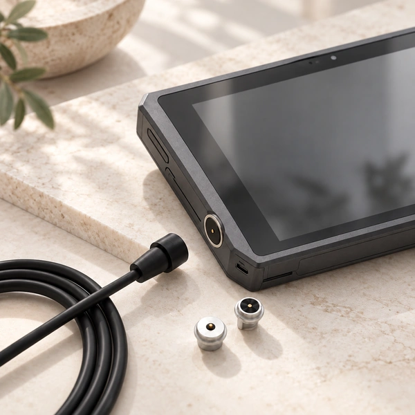
Custom 2 Pin Magnetic Charging Cable for Your Device
Existing housing drawings, PCBA locations, charging contacts and wall thicknesses can be used as the design constraints. We adapt the magnetic assembly to that structure so a standard charger does not force unnecessary device redesign.
Connector Adjustments
Connector dimensions
Pin pitch & definition
Electrical polarity
Magnetic polarity
Waterproof structure
Cable Adjustments
Cable length & OD
Wire gauge (AWG)
USB-A / USB-C / Open wire
Outlet direction
Overmolding design

What Should You Confirm Before Ordering?
Review the following details before requesting OEM prototypes or production parts.
| Parameter | Why It Matters | Information to Provide |
|---|---|---|
| Voltage & Current | Select contacts and conductor size for the current and resulting temperature rise. | e.g., 5V/1A, 12V/3A |
| Pin Pitch | Match the contact centers to the device-side pads. | Center-to-center distance (mm) |
| Connector Dimensions | Fit the magnetic head inside the planned housing opening. | L × W × H (mm) |
| Polarity (Elec. & Mag.) | Check electrical polarity and magnetic attraction to avoid incorrect connection. | Drawing or physical sample |
| Cable Specifications | Review voltage drop, cable routing and the user handling requirements. | Length, AWG, OD, USB type |
| Environmental Requirements | Choose sealing and plating for the environmental conditions. | Confirm based on project spec (e.g., IP rating, Salt Spray) |
| Device-side Connector | If needed, develop the mating device-side connector alongside the cable. | Provide existing PCBA layout |
Scroll horizontally to view every column.
Applications for 2 Pin Magnetic Charging Cables
A two-contact magnetic cable can suit devices with frequent charging, limited space or project-specific sealing requirements.
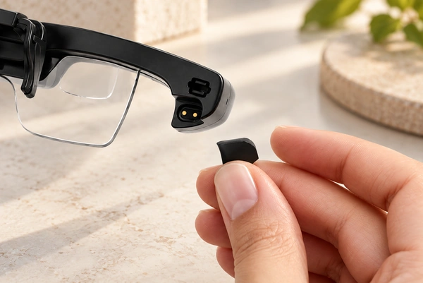
AI Smart Glasses & Wearables
Design constraint: little internal space and frequent charging. Design approach: compact contact pitch with magnetic retention.

Smart Heated Mug
Design constraint: a clean exterior and cleaning with water. Design approach: a round, concealed flush-mount charging interface.
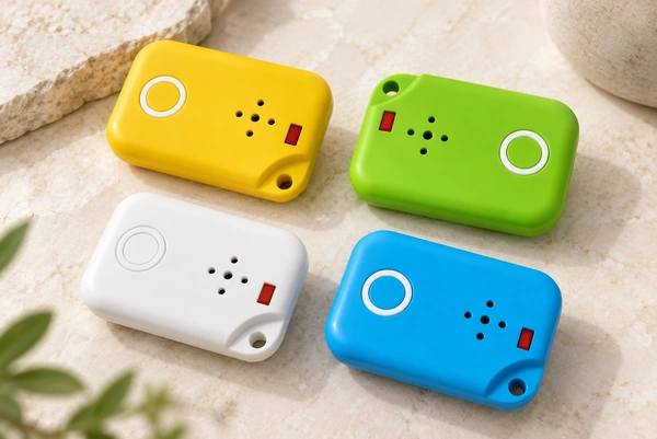
Pet Tracker
Design constraint: vibration, moisture and corrosion. Design approach: sealed overmolding and plating selected for salt spray resistance.
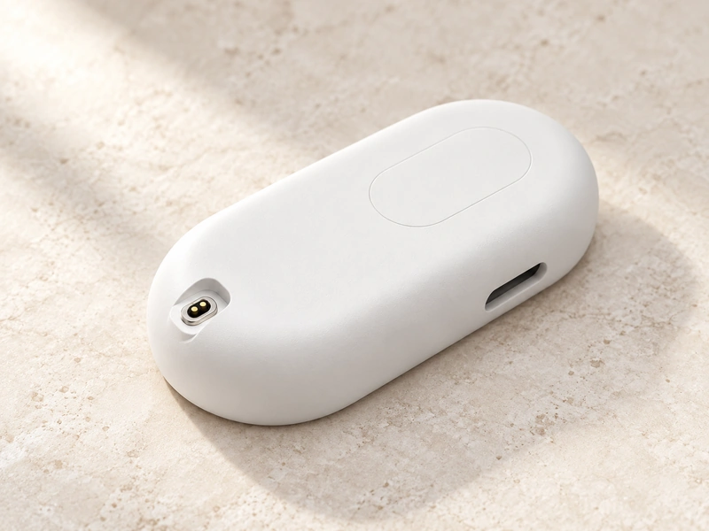
GPS Tracker
Design constraint: cable wear and port damage in field use. Design approach: magnetic release to reduce pulling force on the device port.

Counter LED Lights
Design constraint: quick attachment and release at both ends. Design approach: magnetic interfaces on both ends of the cable.
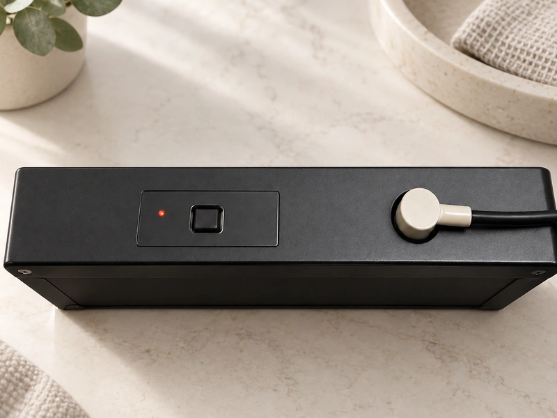
Electronic Scale
Design constraint: exposure to dirt, dust and corrosion. Design approach: plating selected for the connector and pogo pin surfaces.
2 Pin Magnetic Charging Cable vs USB-C
USB-C provides a standardized interface for power and data. A two-contact magnetic connection offers a different mechanical approach for device-specific charging designs.
For charging-only devices, a magnetic head can provide custom enclosure fit, docking without visual alignment and release under a pull. It mates without conventional plug insertion; spring-contact force is still required.
Learn more about Magnetic Cable Connectors| Feature | 2 Pin Magnetic Cable | USB-C |
|---|---|---|
| Electrical Contacts | 2 (Power only) | Up to 24 (Power + Data) |
| User Alignment | Automatic (Magnetic) | Manual insertion required |
| Break-away Safety | Magnetic release under a pull (validate tension) | Plug-in connection may transmit pulling force to the device |
| Device Opening | Customizable surface mount | Deep receptacle cavity |
| Waterproof Design | Easier to seal (flat surface) | Complex internal sealing |
| Standardization | Custom proprietary | Universal standard |
Scroll horizontally to view every column.
Testing and Common Charging Issues
Production testing supports long-term connection performance. During prototyping, the checks below also help identify integration problems before approving the assembly.
Production Testing Protocols
Open / Short circuit
Electrical polarity
Contact resistance
Spring force metrics
Mating cycle endurance
Plating thickness
Insulation / Withstand voltage
Dimensional inspection
Salt spray tests are included when the project specification requires them.
Prototyping Troubleshooting
| Problem | Possible Cause | What to Check |
|---|---|---|
| Connects but does not charge | Polarity or voltage mismatch | Verify pin polarity and power input source |
| Intermittent charging | Working height or contamination | Check pogo compression and clean contact surface |
| Cannot align / Repels | Magnetic polarity reversed | Inspect magnet orientation vs device |
| Cable becomes warm | Current exceeds wire gauge limit | Review cable and connector current specification |
Scroll horizontally to view every column.
Magnetic Cable Manufacturing Capability
Our 12,000 m² facility combines pogo pin manufacturing with custom cable assembly. OEM/ODM support runs from the first engineering review through production at scale.
Certifications & Capabilities:
In-house work includes magnetic cable assembly and pogo pin connector production, with CCD inspection, resistance measurement and mating-cycle tests.

17 Years of Connector Manufacturing
From design to mass production,

Dedicated Connector Factory
A workforce of 185 includes 12 R&D staff at our 12000-square-meter factory. This professional team supports customers with technical and manufacturing services.

Production Equipment and Technical Expertise
Our technical team works with advanced production equipment to maintain consistent connector output and performance.
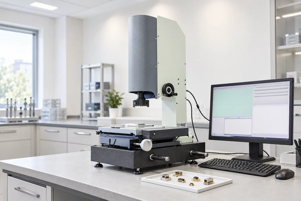
Inspection and Testing
Connector checks include lifespan, film thickness, elastic resistance, RoHS compliance and CCD inspection, using advanced test equipment.
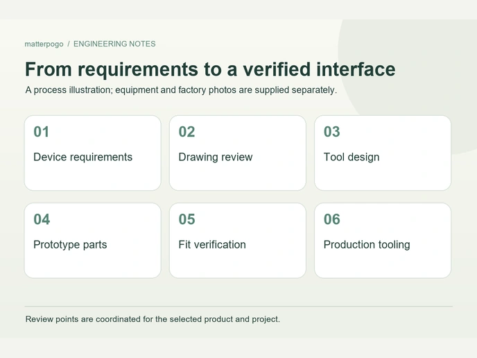
Engineering Support Customers Can Rely On
More than a dozen technical engineers review connector proposals carefully against the requirements of each application.

Automated Production
17 years of manufacturing experience support concept development through mass production, with technical guidance and prompt project responses.
Supporting More Than 500 Enterprises Worldwide








1 / 10
Management Systems and Certificate Documents
ISO 9001
ISO 14001
QC080000
Frequently Asked Questions
Practical selection and integration questions for engineering and procurement teams.
How do I measure the pin spacing of a 2 pin charger?
Can a 2 pin magnetic charging cable use USB-C?
Can the cable length and wire gauge be customized?
Can a 2 pin magnetic charging cable be waterproof?
Why does the magnetic cable connect but not charge?
Can you match an existing cable from a physical sample?
How many mating cycles can a 2 pin magnetic cable handle?
Need a 2 Pin Magnetic Charging Cable for Your Device?
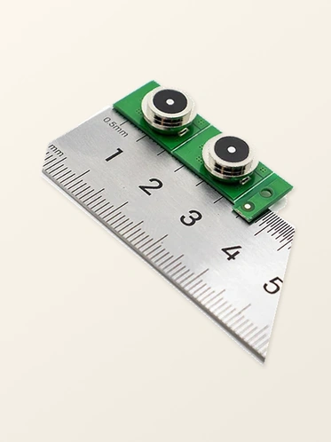
For an existing device-side connector or charging cable, provide its 2D drawing, a sample or key dimensions. Our engineers review those details to determine a matching configuration.
Please prepare to provide:
Device drawing
Connector dimensions
Pin pitch
Voltage / Current
Polarity details
Cable length & USB type
Waterproof requirements
Estimated sample quantity