
Designing a Custom Magnetic Connector Around the Device
Published on September 28, 2026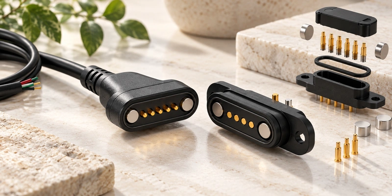
- Define the Device's Requirements
- Develop the Contact Count and Pin Map
- Specify the Spring-Contact System
- Balance Capture, Retention and Release
- Provide Mechanical Positioning and Keying
- Choose Materials, Sealing and Cable Structure
- Validate Prototypes Before Production
- Prepare the Project Information
Develop a custom magnetic interface from the device's electrical, mechanical and environmental needs. Define assignments, pogo-pin stroke and force, magnetic force, alignment, seals, cable or PCB integration and prototype validation together.
magnetic connectorDefine the Device's Requirements
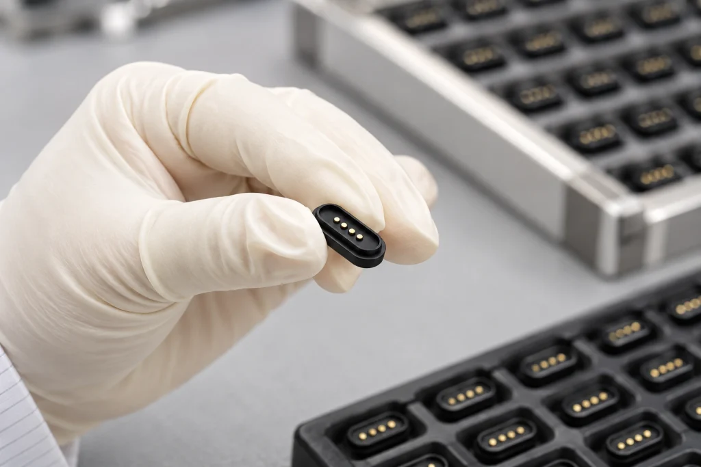
Before choosing the structure, define how the interface will be used and the electrical and environmental conditions it must withstand. Contact count and appearance alone cannot determine a custom design.
Begin with these inputs:
Charging only or charging with data
Operating voltage
Continuous and peak current
Number of power, signal, data or ID circuits
Available installation space
Mating direction
PCB, FPC, wire or cable connection
Required mating cycles
Water and dust protection requirements
Sweat, humidity, cleaning-agent or outdoor exposure
Cable length and end type
A compact wearable may prioritize small dimensions, corrosion protection and convenient capture. A higher-current dock may instead need larger contacts, appropriately selected magnetic retention, low resistance and thermal validation.
Early requirement definition can reduce later mechanical revisions.
Develop the Contact Count and Pin Map
Derive count from electrical functions instead of selecting two, four or six contacts solely because that layout is familiar.
A basic power interface may need:
V+
GND
Detection or identification may use a third path. Power and data together may need additional power, return, signal or ID paths, as determined by the architecture.
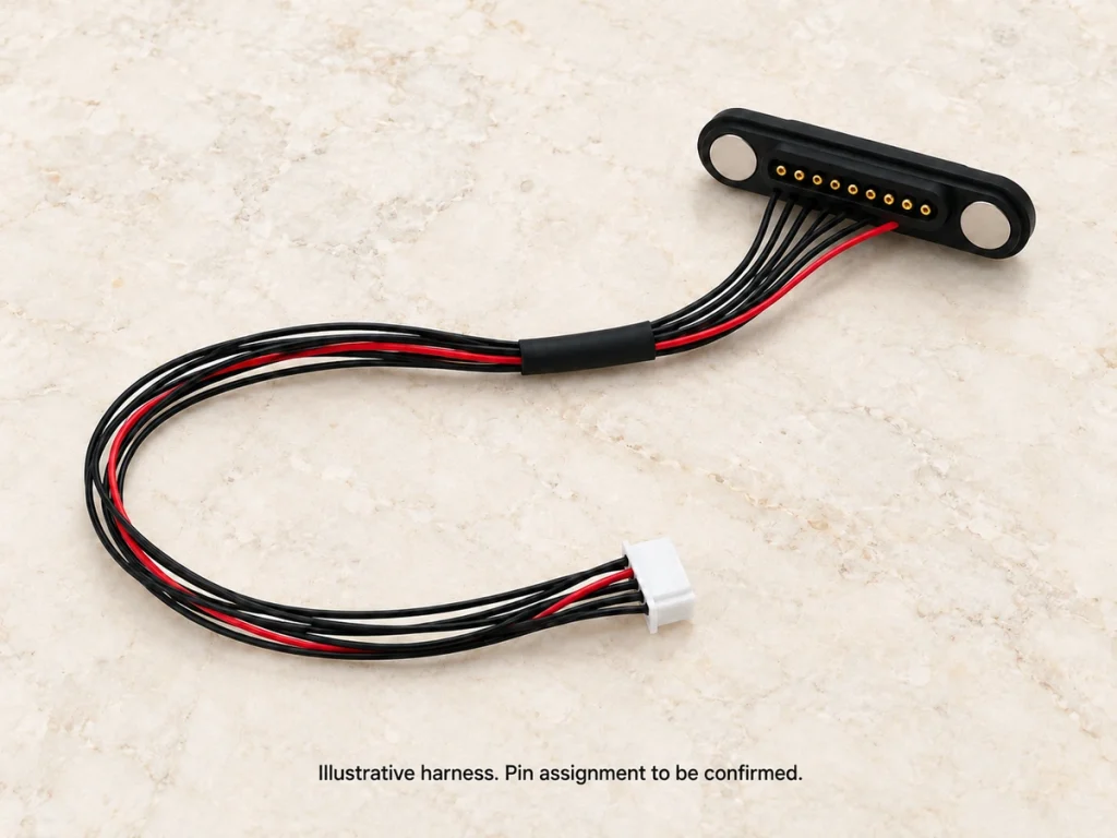
More complex equipment might allocate:
Power
Ground
Data+
Data−
ID
Detection
Control signal
Auxiliary power or signal paths
Options range from simple two-contact charging cables to 4-, 5-, 6- or 8-contact magnetic interfaces with several circuit paths.
2 Pin Magnetic Charging Cable4 Pin, 5 Pin, 6 Pin, or 8 Pin Magnetic ConnectorA higher load may justify more than one power or return contact. Design that allocation deliberately and validate current sharing, resistance and temperature rise.
An early pin map informs dimensions, pin diameter, pitch, PCB routing, conductor count and pad layout.
Specify the Spring-Contact System
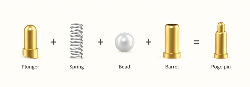
Electrical continuity relies on controlled compression of the spring-contact system.
Specify working stroke, total travel, force, resistance, current rating, diameter, pitch and mating-pad dimensions.
Free height is only one dimension. Check installed height and actual plunger compression when the halves are fully seated.
Too little working compression can leave contact sensitive to tolerances or surface variation. Excessive compression adds spring force and stress and may reduce mechanical life.
All compressed contacts contribute a combined spring reaction. Select magnetic retention to overcome that reaction at the working position while meeting the intended release requirement.
Pitch and pad area must accommodate assembly and alignment tolerances without needlessly enlarging the interface.
Coordinate the contact system with housing, magnets, PCB and mating surface for a compact product.
Balance Capture, Retention and Release
Magnets attract the halves, assist positioning, retain the mate and permit a designed release behavior.
Increasing holding force does not automatically improve the interface.
Set attraction to meet these targets:
Capture the intended mating position
Compress the contacts to their working stroke
Retain electrical contact during normal use
Resist unintended separation caused by device movement
Excessive retention can make removal difficult and transmit unwanted loads to the cable, housing or PCB.
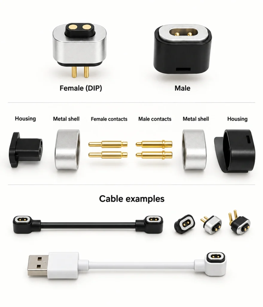
Keep the component roles clear:
Magnet: capture and retention. Housing: precise positioning. Pogo pin: conductive contact.
Review total spring reaction with magnet size, grade, spacing and magnetic circuit. Friction, orientation, device weight and pull direction also affect the actual breakaway force.
For portable and wearable products, a controlled release may reduce the force passed into the device. Validate release for the expected directions and loads.
Provide Mechanical Positioning and Keying
Use mechanical references to control final position alongside magnetic capture.
Locating features can improve repeatability and limit damaging lateral offset at the contacts.
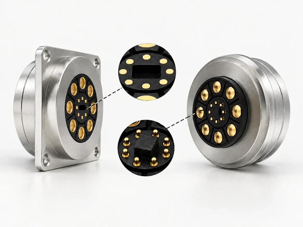
Possible locating and keying features are:
Recessed mating surfaces
Locating bosses
Guide slots
Asymmetric housings
Mechanical stops
Keyed geometry
Specified magnet polarity
These features can discourage reverse mating, reduce offset and set the intended compression. Verify their effect in the completed assembly.
Round, oval, rectangular or custom contours can be selected for installation space and mating direction.
Polarity can assist orientation control. Mechanical keying is also useful where an incorrect mate could join the wrong electrical contacts.
Design the magnetic and mechanical features as one mating system.
Choose Materials, Sealing and Cable Structure
Select materials and structural details for the operating environment.
Moisture, sweat, dust or cleaning liquids may require housing barriers, adhesive seals, O-rings, gaskets or sealed PCB integration. Choose methods for the actual boundary and exposure.
Wearables and medical equipment may need particular attention to sweat, humidity and repeated skin exposure at the mating surfaces.
Select the surface system using:
Expected mating cycles
Contact-resistance requirement
Corrosion exposure
Environmental conditions
Skin-contact requirements
Manufacturing cost
Gold can provide a conductive, corrosion-resistant contact surface, but the underlayers and thickness need application-specific selection. Avoid applying one plating specification to every project.
For a cable assembly, define its structure and end options:
90° cable exit
180° straight exit
USB-A
- USB-C
Bare wire
Terminal end
Custom end connector
Match length, wire gauge, conductor count, shielding, strain relief and jacket material to the device's electrical and mechanical requirements.
Validate Prototypes Before Production
A CAD fit does not replace validation inside the actual device.
Check prototype electrical performance and mechanical compatibility before final tooling or production approval.
Plan the following validation groups:
Electrical Checks
Contact resistance
Voltage drop
Continuous current
Peak current
Temperature rise
Signal or data continuity
Mechanical Checks
Working stroke
Spring force
Magnetic holding force
Breakaway force
Cable pull force
Mating-cycle life
Environmental Checks
Water-protection performance
Salt-spray exposure
Sweat or corrosion resistance
High- and low-temperature exposure
Humidity exposure
Dimensional Checks
Contact pitch
Contact positions
Housing dimensions
Installed height
Mating gap
Assembly tolerance
PCB thickness, housing dimensions, adhesives, stops, pad height and magnet position together create the final working condition. Evaluate the assembled system.
Before production, verify performance across the expected dimensional tolerance range instead of relying on one ideally positioned sample.
Prepare the Project Information
Complete project information can reduce avoidable development revisions and help the engineering review proceed.
Provide:
Product application
Required contact count
Pin map
Operating voltage
Continuous and peak current
Maximum connector dimensions
PCB or housing installation space
Mating direction
- Water-protection requirement
Target magnetic holding force
Expected mating cycles
PCB, FPC or cable connection
Cable length
USB, bare-wire, terminal or custom end
2D or 3D device drawings
Prototype quantity
Expected production volume
With these inputs, assess magnets, pogo pins, housing, cable and mating interface as a complete connection system.
Developing a Coordinated OEM Interface
Magtor can assess OEM magnetic configurations against electrical, mechanical, environmental and assembly requirements, including contact layout, cable ends, magnetic positioning, seals and prototype validation.
MagtorCoordinate conductive contacts, spring force, magnetic force, alignment, environmental protection and device integration so the interface works as one engineered system.
Frequently Asked Questions
Can a custom magnetic interface carry charging and data together?
Yes, when paths are allocated for power, data, ID or control and the complete electrical design supports them. Define the device interface, current, protocol, available space and circuit requirements for the configuration.
At what stage should the connector supplier join the project?
Involve the supplier during early mechanical and electrical design. Review dimensions, PCB position, mating direction, cable routing and enclosure space before the structure is finalized to reduce later revisions.
Can an existing platform be adapted?
It may be possible when dimensions and functions are close. Assess changes to count, length, ends, finish, magnet arrangement, housing details and wire specification. A new structure may be needed for substantially different space, layout, geometry or performance.
Which inputs affect development cost?
Cost depends on size, mechanical complexity, tooling, magnet structure, contact count, sealing, cable construction, plating, testing and projected volume. Reusing a compatible platform may reduce tooling and development work.
Which information supports quotation and prototyping?
Provide a 2D or 3D drawing, application, voltage and current, available space, mating direction, cable specification, projected volume and target schedule. Include a preliminary pin map or device-side layout where available to support the review.