
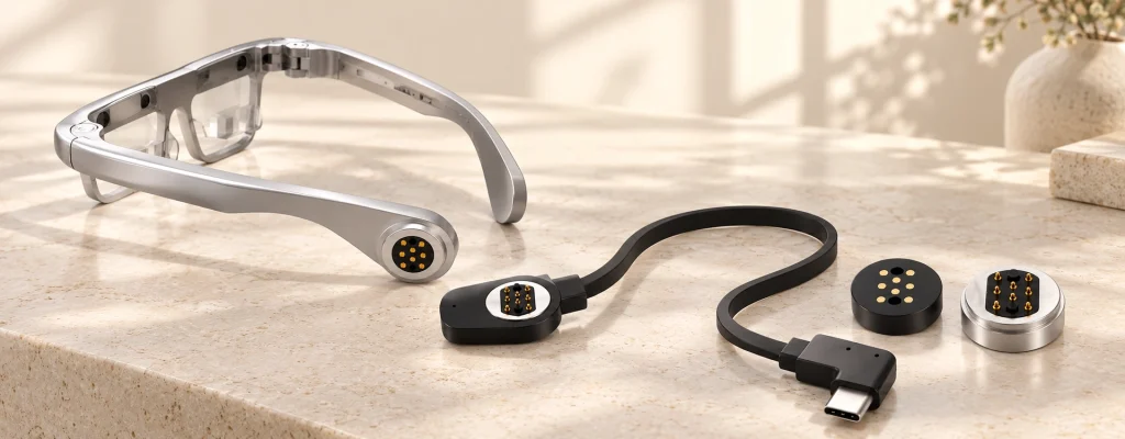
8-Pin Magnetic Cable Assemblies for Multi-Circuit Devices
Develop a complete cable assembly with an eight-contact magnetic head. Independent power, signal and control paths can be defined with USB, bare-wire or custom ends to match the device-side interface.
- Home
- Magnetic Cable Connector
- 8 Pin Magnetic Charging Cable
8 Pin Magnetic Cable Connector Options
Select the assembly structure around the integration requirements of your device.
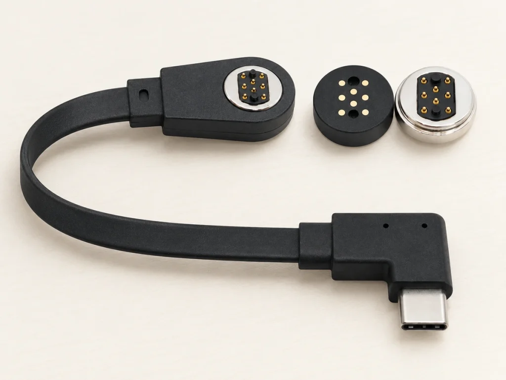
8 Pin Magnetic Charging Cable
USB-A or USB-C ends can serve external charging or suitable host data connections. The full assembly mates with the device-side interface, with electrical functions defined by the approved wiring and circuit.
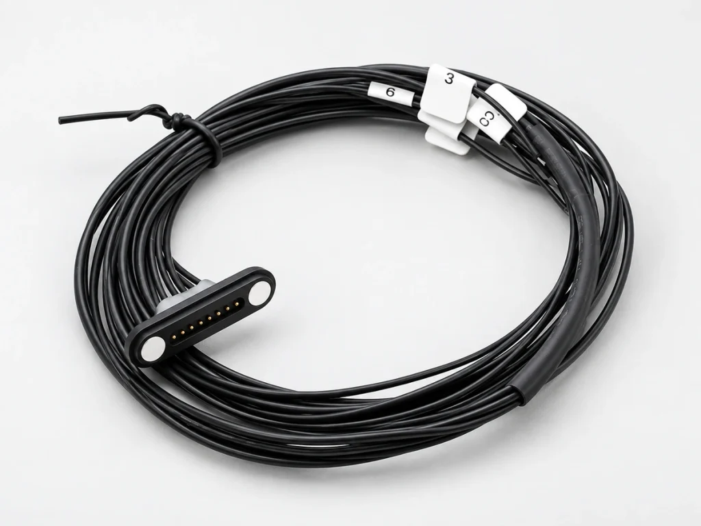
8 Pin Magnetic Connector Cable Bare Wire
Open conductors support internal harnesses and direct PCB soldering. Specify color, gauge, strip length and conductor routing to match the contact map.
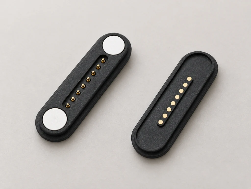
8 Pin Magnetic Connector
The standalone male or female component is integrated into the PCB and enclosure. Review working stroke, spring force and magnetic polarity with its mating structure.
View More Magnetic Connectors8 Pin Magnetic Cable Connector Specifications
Housing shape, magnet layout and contact arrangement vary across eight-contact products. Select the structure before confirming the project specifications.
Reference Config (8 Pin Magnetic Charging Cable)
8PIN M/F, 2.50mm Pitch/2.00mm Pitch
These reference specifications relate to the two cable formats above. Retention and conductor construction depend on the model. Ask Magtor for the 2D drawing of the configuration you are considering.
| Parameter | Specification Range / Status |
|---|---|
| Pin Count | 8 Contacts (Configurable allocation) |
| Pin Pitch | Model dependent (e.g., 2.0mm, 2.50mm) |
| Rated Current | Defined by selected structure (e.g., 2A–5A) |
| Magnetic Force | Model dependent (e.g., approx. 880gf) |
| Connector Shape | Round / Rectangular / Custom |
| Cable Length & Gauge | Project dependent |
| Cable End | USB-A, USB-C, Bare Wire, Internal Terminal |
| Waterproof Option | Available according to project requirements |
Scroll horizontally to view every column.
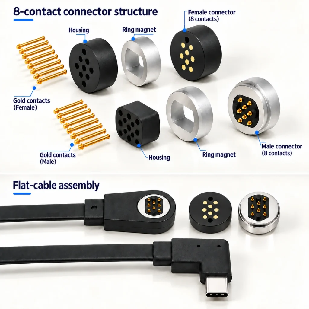
What Is an 8 Pin Magnetic Cable Connector?
An eight-contact magnetic cable is a detachable assembly with a magnetic head, conductors and a specified end, such as USB or bare wire.
Eight paths give engineers room for power, signals, ID, detection and control. The cable-side assembly pairs with a specified device-side magnetic connector; it is distinct from the standalone PCB component.
Why Use 8 Contacts in a Magnetic Connector?
For a device that needs more than power and ground, eight contacts can combine several functions in one port. The additional contacts provide more circuit-allocation options.
Define each path from the schematic: additional power returns, signals, ID, detection, control or reserved functions are possible. Eight physical contacts do not automatically support eight communication protocols.
Discuss Your Circuit Allocation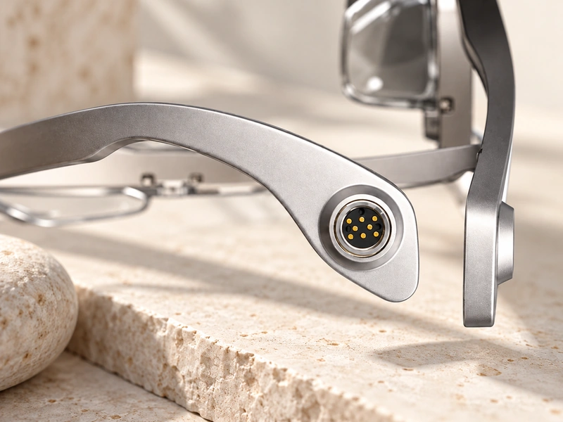
Allocation Options
Power / Ground
Signal / Data
ID / Detect
Control / Auxiliary
Is There a Standard 8 Pin Magnetic Connector Pinout?
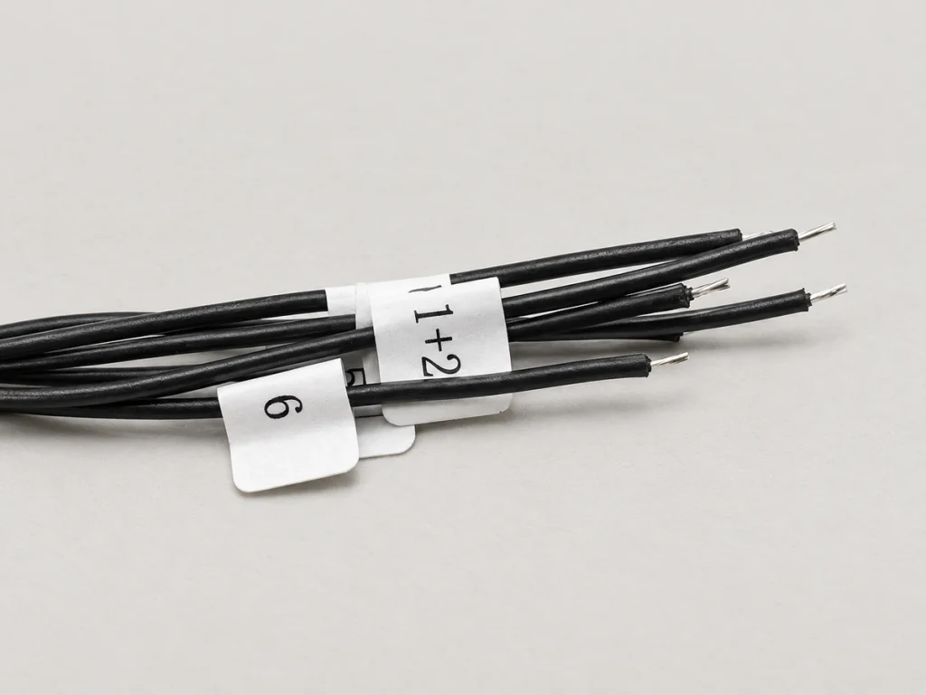
No universal eight-contact magnetic pinout applies.
Contact functions are set by the schematic, power architecture, PCB layout and mating orientation. The contact count defines the physical interface.
Example Circuit Allocation:
Pin 1: Power (V+)
Pin 2: Ground (GND)
Pin 3: Signal 1
Pin 4: Signal 2
Pin 5: ID
Pin 6: Detect
Pin 7: Control
Pin 8: Reserved
The contact map shown is an example, not a universal eight-contact standard.
Choose the Cable Termination for Your Device
Select the opposite cable end for the source connection or internal assembly method.
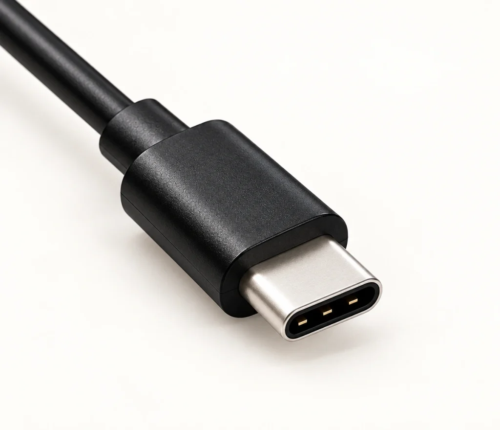
USB-C
For suitable external charging sources and host connections.
USB-A
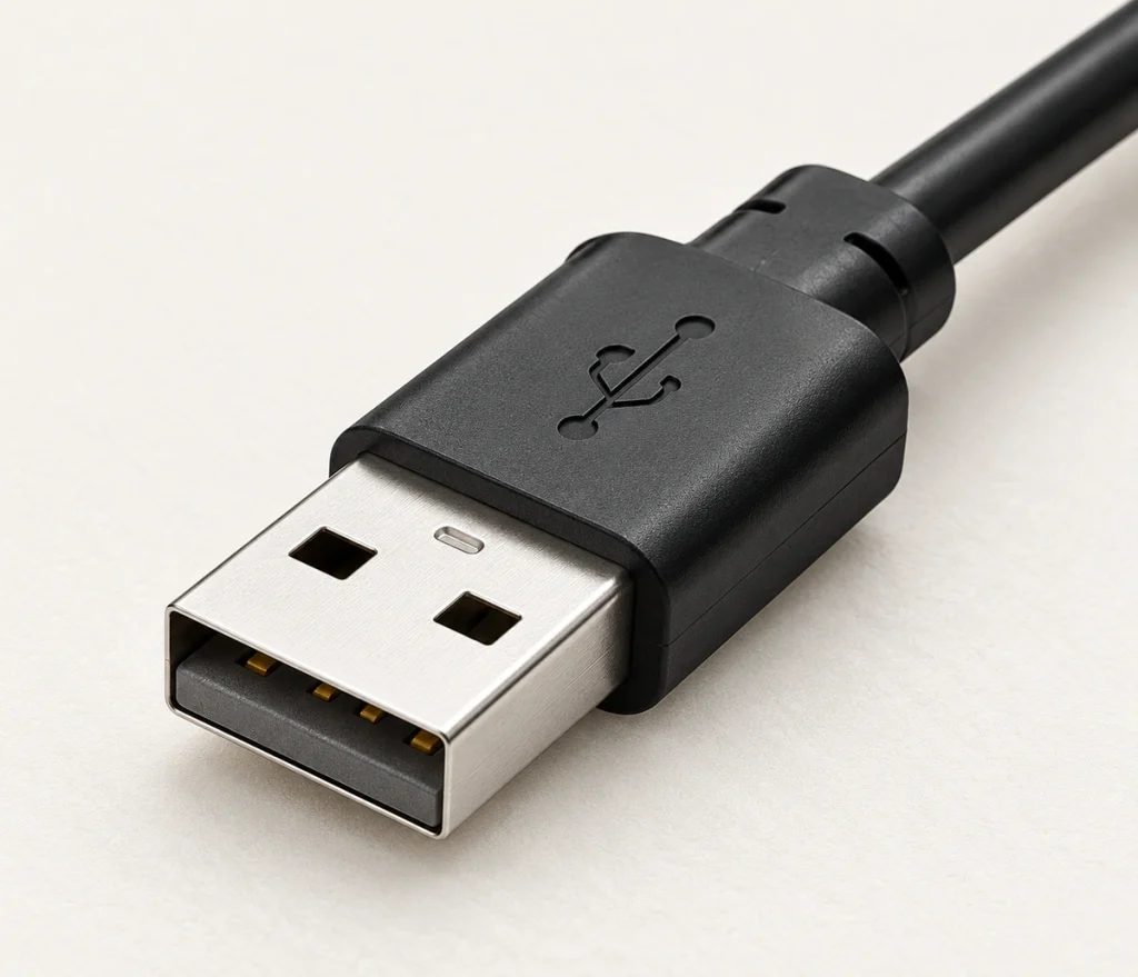
For conventional charging docks and USB power sources.
Bare Wire
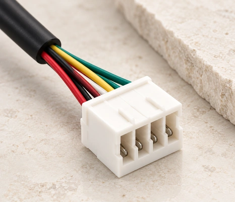
For prototypes, direct PCB soldering and wiring inside an enclosure.
Internal Terminal
Match the terminal to the production harness and internal PCB connector.
Where Are 8 Pin Magnetic Cable Connectors Used?
Eight contacts can serve devices that need additional circuits alongside charging.

Medical Electronics
Medical devices may need ID, detection or signal paths beside charging. Define those functions strictly from the device circuit and validate the full system.

Industrial Handheld Devices
Industrial handhelds can combine power, device detection and control with a quickly docked field interface.

Robotics
Robotics can route several sensor-return paths or auxiliary power through one detachable interface. Confirm the current distribution for the assembly.
Smart Hardware
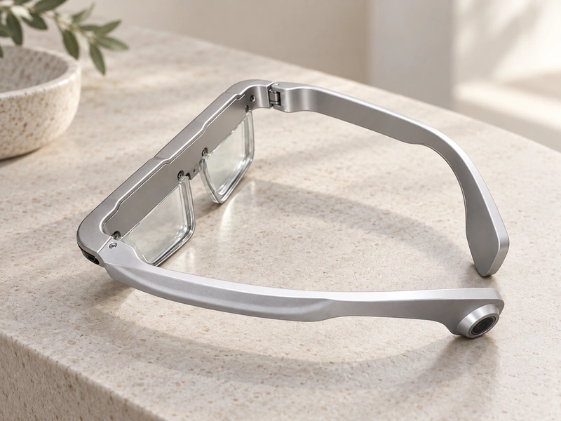
Complex wearables and portable docking systems can combine their power and data circuits in one interface.
Testing an 8 Pin Cable Before Production
Validate electrical and mechanical performance before pilot production. Specify the tests and conditions around the project requirements.
Cable Continuity Testing
Check all eight conductors against the approved map to identify open circuits, shorts and incorrect wiring before approval.
Contact Resistance & Cycle-Life
Resistance measurements identify unstable contact paths. Cycle testing evaluates repeated magnetic docking.
Spring Force & Dimensional Inspection
Check contact compression and housing dimensions where tolerances affect the mating interface.
Environmental Testing
Salt spray and temperature-rise tests can assess corrosion resistance and loaded-circuit thermal behavior for the required environment.

From Interface Definition to Production
Sample timing depends on whether an existing interface can be used or new housing, tooling or cable-end development is needed.
Requirement Review
Review device drawings, PCB layout and the contact map.
Specification
Define the 2D design, cable length and conductor gauge.
Prototype & Validation
Evaluate electrical and mechanical prototype performance.
Sample Approval
Obtain customer validation and approval.
Mass Production
Run a pilot batch and check volume-production consistency.

Engineering and Manufacturing Behind the Connector
Magtor operates a Dongguan factory of approximately 12,000 m² with around 185 employees and a dedicated 12-person R&D team. This series lists an establishment year of 2009, which remains to be confirmed.
ISO 9001, ISO 14001 and QC 080000 management systems support manufacturing processes. Contact tolerances, spring-force consistency and repeatable assembly are reviewed for complex eight-contact designs. In-house capabilities include pogo pins, magnetic connectors and USB Type-C cables for OEM projects across industries.
Customer Relationships Include
Supporting More Than 500 Enterprises Worldwide










1 / 10
Management Systems and Certificate Documents

ISO 9001
ISO 14001
QC080000