
Four-Contact Magnetic and Pogo Interfaces: How to Choose
Published on October 6, 2026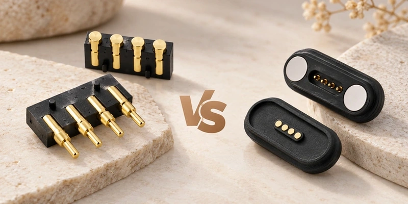
- Four-Contact Magnetic Interface Architecture
- Comparing Alignment and Retention
- Electrical and Mechanical Requirements
- Potential Applications
- Selecting the Mating Method
- Customizing the Four-Contact Assembly
- Design Questions
A four-contact magnetic interface can use pogo pins with magnetic guidance. A conventional four-contact pogo assembly uses spring contacts, with positioning and retention supplied by its surrounding mechanical design. Both may carry power or signals; compare how the complete mates align, stay engaged and connect.
For engineering and purchasing review, define current, contact arrangement, mating frequency, available space, alignment needs, cable configuration and environmental exposure. Those seven inputs guide the choice.
Four-Contact Magnetic Interface Architecture
In a pogo-based four-contact magnetic design, housing magnets guide the approaching halves and four spring contacts touch their mates to conduct electricity. The magnetic function assists positioning; electrical transfer still requires conductive contact.
Four-Contact Magnetic AssemblyGuided mating can assist a detachable connection by reducing the precision needed for manual positioning. Assign the four contacts to the required power, return and signal functions. That allocation does not establish a communication protocol by itself.
signal connections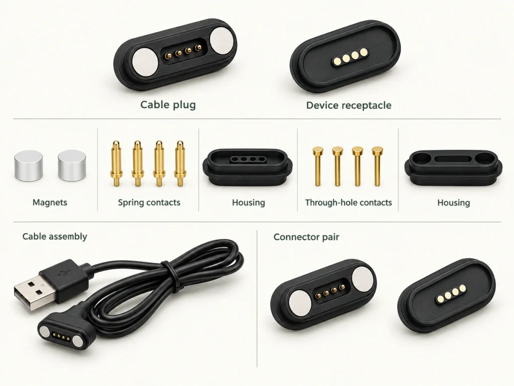
Mechanical options may include straight, 90° or 180° cable configurations and round, square or rectangular housings. Choose the combination around installation space and cable routing.
Custom dimensions, contact layout, magnetic force, cable length and housing construction can be developed around the device's mechanical and electrical requirements. Review those five inputs before agreeing the structure.
Comparing Alignment and Retention
Pogo contacts can be present in both assemblies. The magnetic version adds a magnetic positioning and mating system, so the meaningful comparison is the complete interface architecture.
| Feature | Four-Contact Magnetic Assembly | Four-Contact Pogo Assembly |
|---|---|---|
| Pogo contacts | Present in the architecture compared here | Present in the architecture compared here |
| Magnetic alignment | Provided by a suitable magnetic design | Usually absent unless separately added |
| Blind mating | Can be assisted by magnetic and mechanical guidance | Depends on the mechanical design |
| Detachable connection | Possible with suitable retention and release force | Possible where the assembly permits it |
| Power transfer | Possible within validated electrical limits | Possible within validated electrical limits |
| Signal transfer | Possible with a suitable complete signal path | Possible with a suitable complete signal path |
| Custom contact layout | Can be designed for the device | Can be designed for the device |
| Cable assembly | A cable configuration can be developed | Depends on the design |
| Water protection | Requires a suitable sealed assembly and verification | Requires a suitable sealed assembly and verification |
| Magnetic retention | Provided by the designed magnetic system | Absent unless separately designed |
Scroll horizontally to view every column.
Conventional pogo contacts can suit a position already controlled by the housing, PCB, fixture or dock. Magnetic guidance may help when users need easier alignment or frequent attachment and removal.
PCBSelect from the complete interface design, including the positioning and retention mechanism behind the connector name.
Electrical and Mechanical Requirements
Four contacts do not define electrical performance. Specify the contact structure and complete cable or connector assembly together for either architecture.
Set the required current, then evaluate contact size, spring structure, conductors, cable specification and allowable temperature rise. The rating must apply to the assembled current path.
Rated current
Allocate the contacts from the device circuit. Four positions can serve different power and signal combinations, but no universal magnetic four-pin map applies. Confirm the actual assignment and orientation on the agreed drawing.
For repeated mating, review resistance and the plating system alongside contact material, spring force and geometry. These features interact as surfaces and contact pressure change during use.
Mechanical review covers installation space, connector orientation, cable exit, magnetic force, housing dimensions and mating direction. Moisture, sweat, dust and cleaning exposure also require an application-specific sealing and protection review.
Specify these inputs as a coordinated set; contact count is only one selection factor.
Potential Applications
Consider a four-contact magnetic assembly when the electrical interface also needs guided, convenient mechanical mating.
Wearable and portable devices may benefit from magnetic guidance where charging or power cables are attached and removed frequently.
A detachable magnetic charging interface can reduce the need to insert a conventional plug and socket on each connection. Charging capability still depends on the complete electrical design.
magnetic connectorSmart-device designs can allocate four contacts to power and selected signals within one interface, provided the circuit and signal path support those functions.
Medical and industrial equipment may consider guided detachable mating. Evaluate electrical ratings, mechanical retention, environmental sealing and equipment reliability requirements for the intended design. The architecture does not establish medical qualification or suitability on its own.
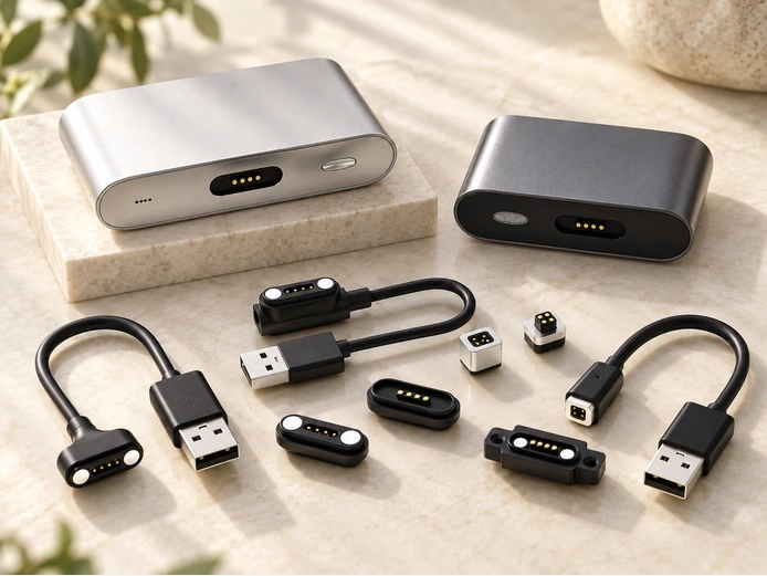
The relevant benefit is the combination of four conductive contacts and guided magnetic mating in one assembly.
Selecting the Mating Method
Begin with device requirements, then decide how its contacts should be positioned and retained.
Consider magnetic guidance for these six needs:
Magnetic positioning
Easier or blind mating with suitable guidance
Frequent attachment and removal
A detachable cable interface
Guided positioning of the mating halves
A custom combination of electrical and mechanical features
A conventional four-contact pogo assembly may suit these five needs:
A fixed contact interface
PCB-to-device contact
Internal electrical connections
Mechanically controlled mating position
No need for magnetic guidance
A fixed internal interface may gain little from magnetic alignment. A user-operated charging mate may benefit from it. Compare those use conditions rather than treating one architecture as the best choice for every device.
Base the decision on current, contact configuration, available space, cycles, environmental conditions, cable routing and the intended user experience. Review all seven factors for the proposed mate.
Customizing the Four-Contact Assembly
Custom design is an option when available dimensions or electrical configurations do not match the application.
Depending on the project, changes may cover contact arrangement, housing dimensions, magnetic force, contact structure, cable length, cable exit, connector orientation, plating and sealing construction.
Limited space may call for a smaller housing; a side-mounted cable may call for a 90° configuration. Water or cleaning exposure may require a sealed structure qualified for that environment. These examples describe design needs, not existing protection ratings.
Define current, operating voltage, signals, assignments, cable specification and mating cycles early. Each of these six inputs can influence the mechanical and conductive structure.
Magtor can develop a four-contact magnetic configuration around the project's electrical, mechanical, cable and installation requirements. The design combines four conductive contacts with the agreed magnetic guidance system.
MagtorDesign Questions
Do four-contact magnetic interfaces use pogo pins?
Many do. Their magnets assist positioning while spring-loaded pogo contacts establish the conductive connection. Confirm the actual contact structure for the selected design.
How do magnetic and pogo functions differ?
Pogo pins provide compliant conductive contact. A magnetic assembly may use the same contact type while adding magnetic guidance and detachable mating; the functions can be combined in one connector.
Can four contacts carry power and data?
They may be assigned to those functions if the device design supports them. A particular power or signal requirement depends on contacts, cable and assembly specifications; four positions alone establish no protocol or rate.
Can the four-contact assembly be sealed?
A suitable housing, seal and contact structure can be developed for water protection. Define the required level and environmental conditions, then verify the complete assembly.
Can the contact layout be changed?
Contact arrangement, housing dimensions, magnetic structure, cable configuration and other mechanical or electrical inputs can be adapted to the specific application after engineering review.