
8-Pin Magnetic Interfaces with Stable Docking
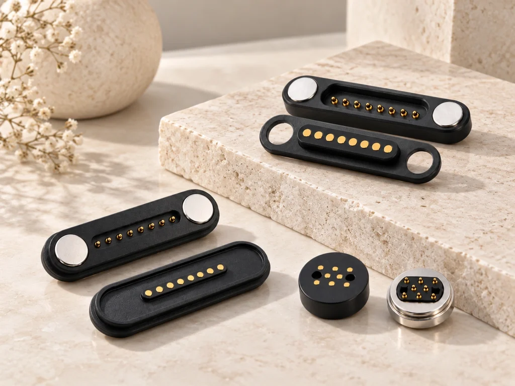
Eight spring-loaded electrical contacts work with magnetic alignment to connect power, signals, ID, detection or control circuits. Rectangular and round male/female structures can be adapted to a custom device. For a complete cable assembly, see the Magtor 8-Pin Magnetic Cable Connector series.
8 Pin Magnetic Cable Connector17 Years Factory Direct
Custom OEM Solutions
Stable Current Transmission
Precision Prototyping
For an engineering review, provide the contact map, voltage and current, installation space and expected quantity.
- Home
- Magnetic Connector
- 8 Pin Magnetic Connector
Select an 8-Contact Structure
Match the connector structure to your mechanical layout and environmental requirements.
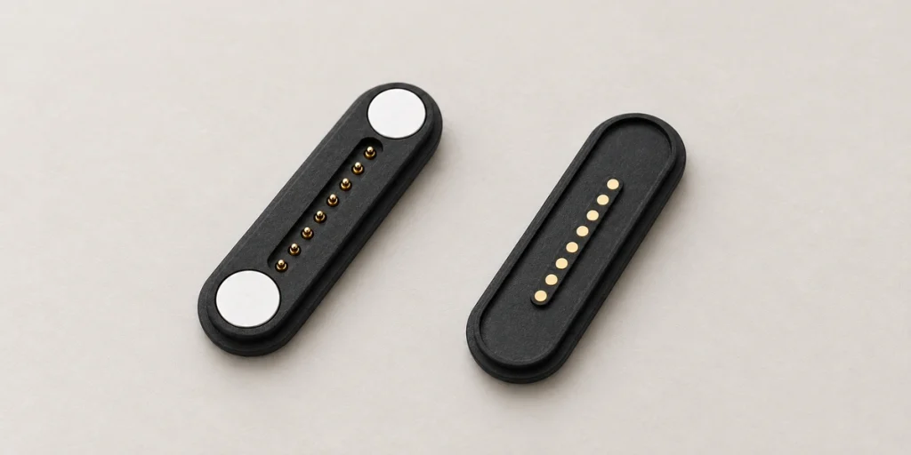
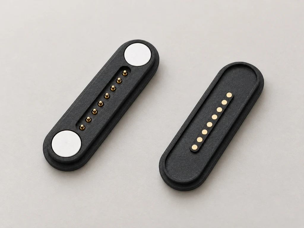
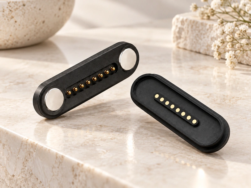
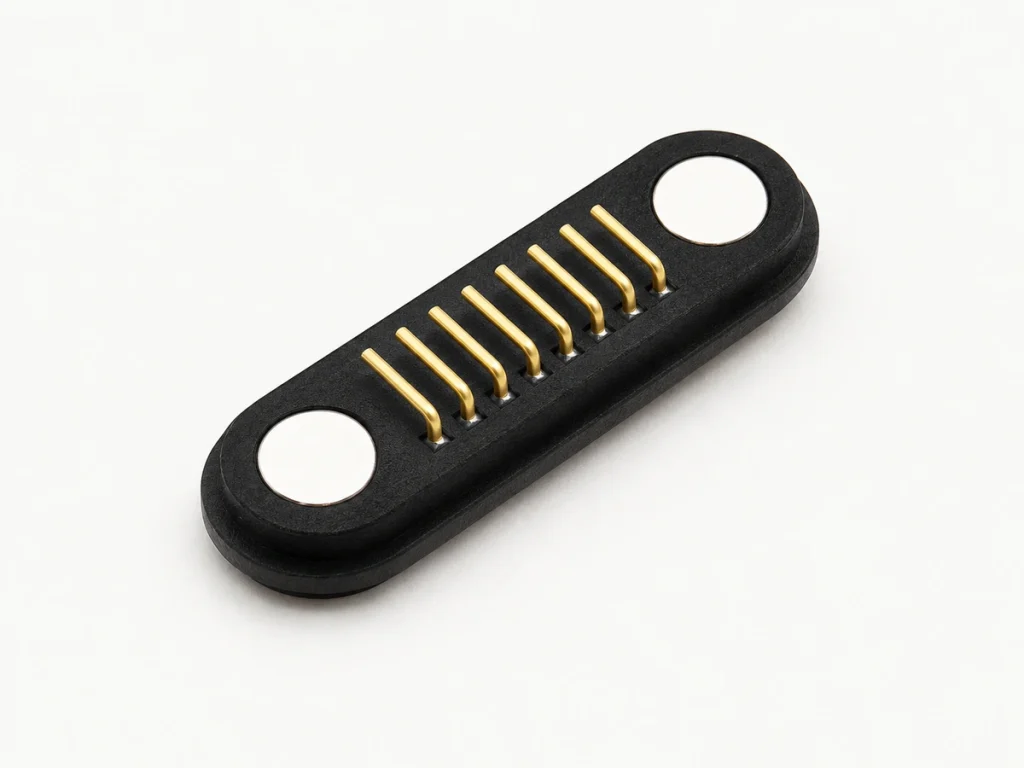
Oblong shape 8 Pin Magnetic Pogo Pin Connector
An oblong structure can suit compact layouts, with sealing and environmental protection developed where applicable.
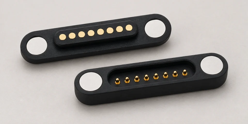
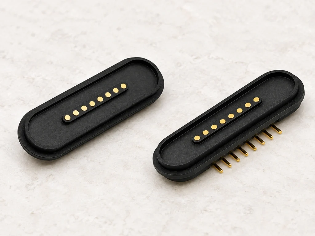
8 Pin Pogo Pin Magnetic Connector
A rectangular male/female PCB interface combines power, signals and multiple circuits.
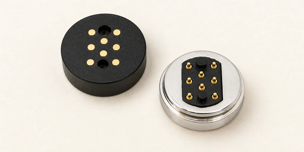
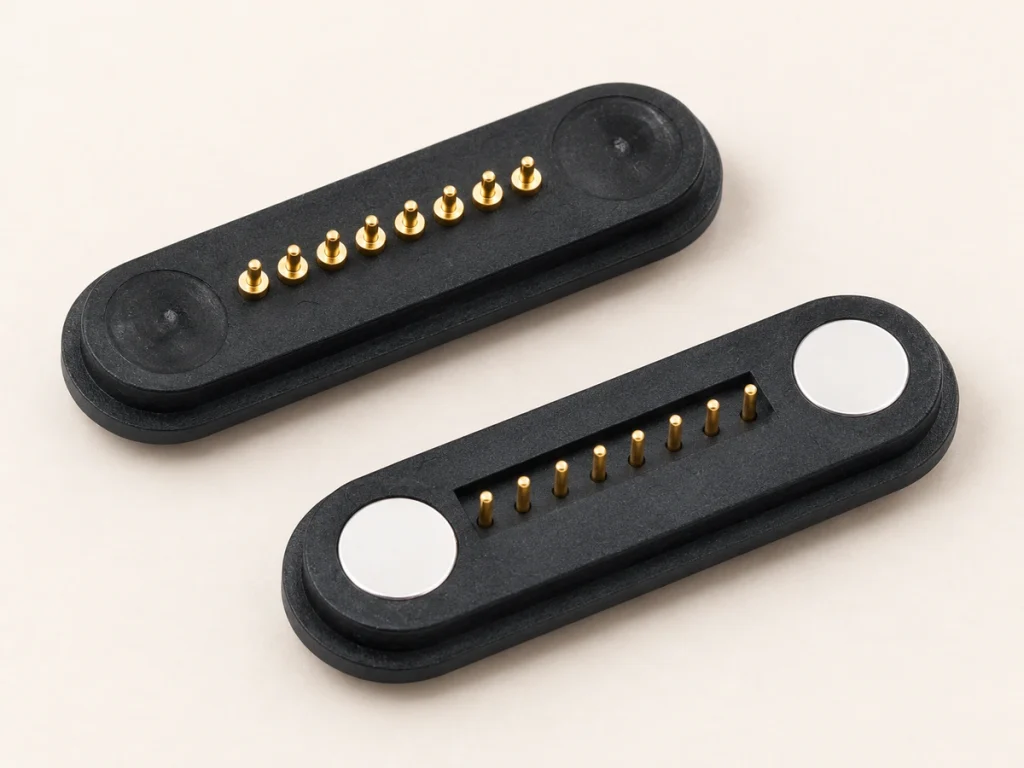
Round 8 Pin Magnetic Connector
A round layout suits circular installation spaces and compact docking arrangements with multiple alignment approaches. Confirm contact mapping for the intended orientation.
1 / 3
Standard 8-Pin Magnetic Connector Specifications
Contact pins are offered in straight and bent arrangements.
Quick Specifications
Rectangular vs Round 8 Pin Magnetic Connectors
Choose the shape around the installation space, PCB routing and intended docking motion.
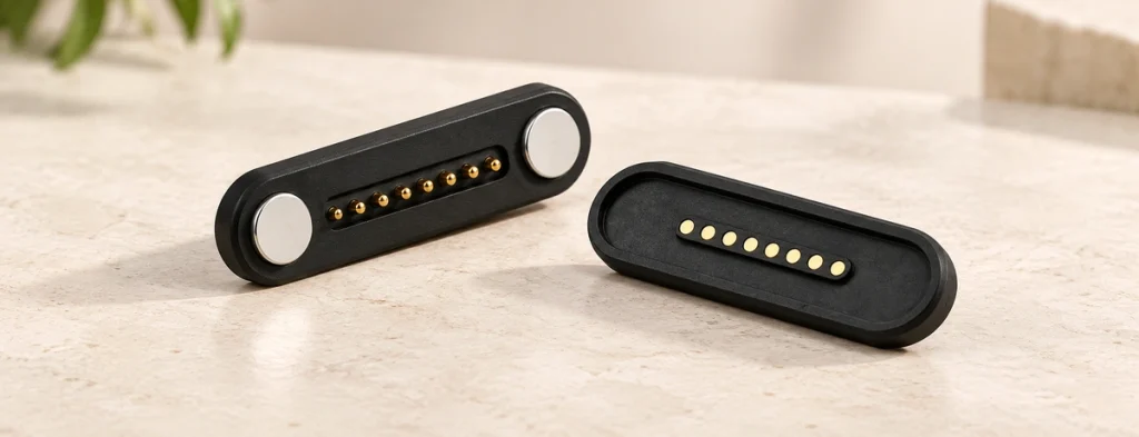
Oblong shape
A linear contact map simplifies routing to the PCB.
The mating orientation must be defined, often for one-way docking.
A suitable choice for wide, flat installation areas.
Pin pitch and overall length can be customized.
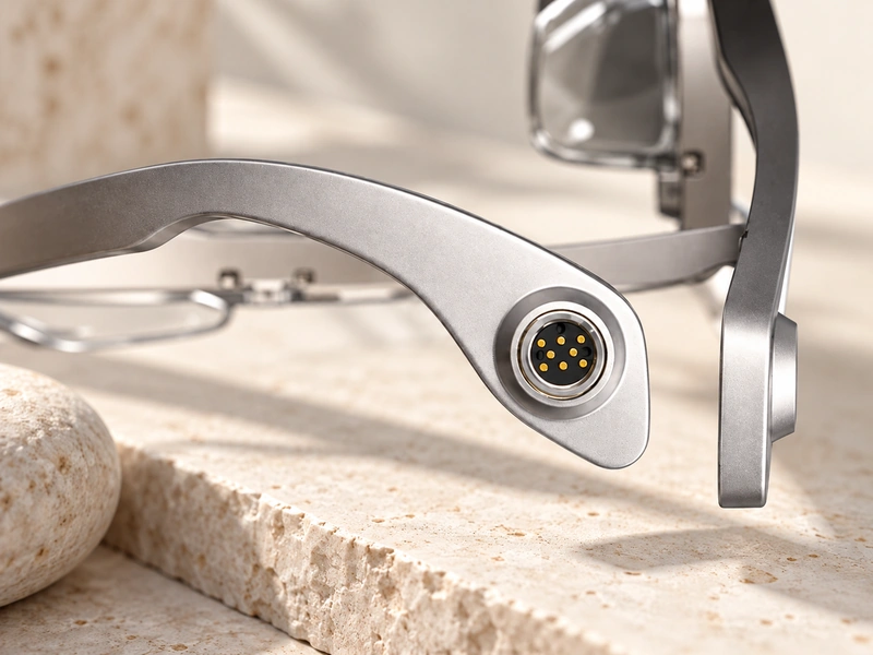
Round
Circular pin layout.
Plastic locating posts stabilize alignment during docking.
A suitable shape for cylindrical housings or small circular spaces.
Magnetic retention holds the docking interface in place.
What Is an 8 Pin Magnetic Connector?
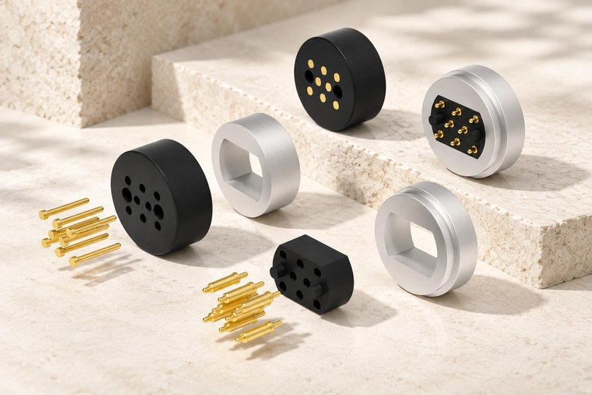
Magnets align and retain the mating parts of this electromechanical interface. Spring-loaded pogo pins create the electrical contact.
Magnets: guide alignment and retain the parts during docking.
Pogo pins: apply spring-loaded contact pressure during shock or vibration, subject to design validation.
Female contacts/pads: provide the mating conductive surfaces on the device.
Eight contacts: assigned to project-specific power, ground, signals, ID, detection or control.
There is no universal eight-contact pinout. Each project requires its own assignment.
Our Magnetic Pogo Pin Connectors overview explains the underlying contact technology.
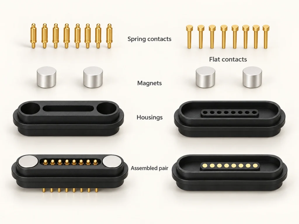
Magnetic Pogo Pin ConnectorsMale and Female 8 Pin Magnetic Connector Structure
Match the spring-contact side to its mating contact surfaces for a stable connection.
The assembly combines male pogo pins, female contacts, magnets, housing parts and a PCB or soldering interface. Review matched drawings for the following mechanical details:
How Can the 8 Pins Be Assigned?
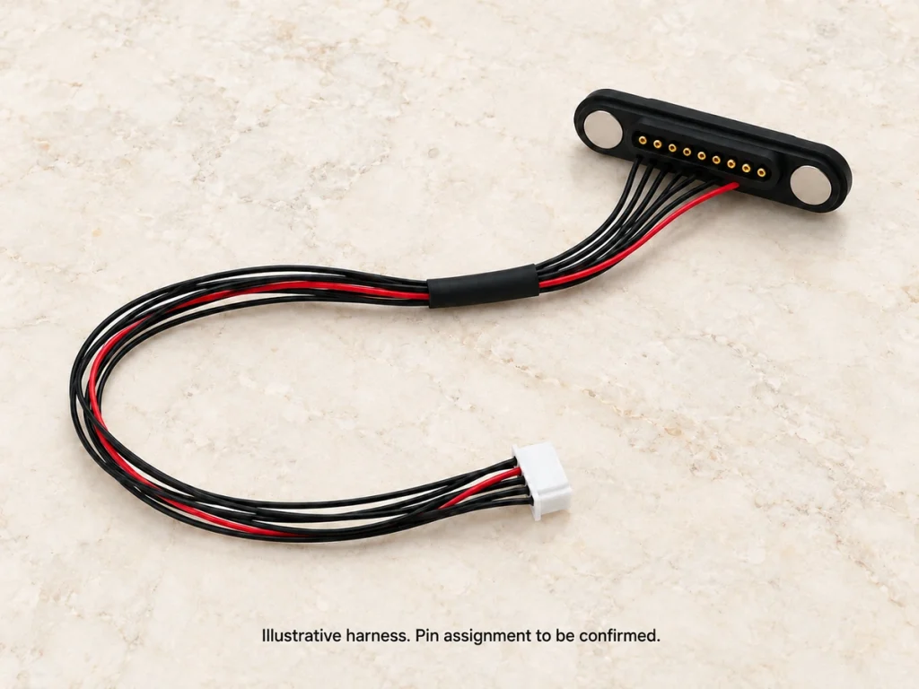
There is no universal 8-pin magnetic connector pinout.
The device architecture determines the final OEM contact map. Review these electrical and protection requirements before assigning the eight contacts:
Voltage requirements
Continuous current
Peak current loads
Data protocol
Ground return paths
Contact sequence (make-first, break-last)
Hot-plug strategies
Device protection circuits
Magnetic Alignment for Repeated Docking
Handheld terminals, portable instruments and medical equipment may dock repeatedly throughout a work shift. Wear and alignment therefore affect maintenance. Magnetic capture guides the parts into position, and spring contacts apply pressure once the parts meet.
Approach: bring the male and female parts together.
Magnetic capture: opposing magnetic poles attract.
Alignment: housing geometry guides the intended mating position.
Contact compression: the pogo pins meet the mating surfaces and compress.
Electrical connection: the assigned contacts carry current, signals and data.
Retention cannot be assessed from magnetic force alone. Check alignment tolerance, mating direction, housing clearance, working height, polarity, lateral loads and the direction of release.
Waterproof and Environmental Options
Sweat, dust, humidity, cleaning agents and industrial contamination all influence the required environmental protection.
Rear adhesive sealing is one approach used on applicable standard designs for IP65–IP67 protection. Other models may have no waterproof rating. Corrosion protection also depends on the engineering choices below; verify the exact completed configuration.
Gold-plated contacts support low resistance and resistance to oxidation.
Ni-Cu-Ni plating helps protect magnets against moisture.
Housing seals can use insert molding or O-rings.
Select plating thickness for the project and evaluate it through salt spray testing.
Plating, environment, applied voltage, chemicals, wear and the overall device sealing design determine the final environmental performance.
Where Are 8 Pin Magnetic Connectors Used?
Review the device constraints, contact approach and expected benefit of each application.
Smart Wearables
Design constraint: skin contact and sweat.
Design approach: flush gold-plated female pads in a sealed housing.
Expected benefit: improved corrosion protection and charging without visual alignment; verify device safety.
Medical Electronics
Design constraint: sterilization and safety.
Design approach: high-cycle spring contacts with magnetic release.
Expected benefit: cable release can reduce pulling risks to patients and equipment.
Portable Instruments
Design constraint: vibration and data continuity.
Design approach: separate power and signal contacts in an eight-contact array, retained by NdFeB magnets.
Expected benefit: stable electrical continuity during movement, subject to validation.
Industrial Handhelds
Design constraint: frequent docking.
Design approach: spring-force optimization for 10,000+ mating cycles.
Expected benefit: reliable charging after a shift with reduced interface wear.
Beauty Devices
Design constraint: exposure to liquids.
Design approach: integrate an applicable IP-rated structure.
Expected benefit: reduce exposure of internal circuits to gels and cleaning fluids; confirm chemical compatibility.
IoT / Smart Devices
Design constraint: limited installation space.
Design approach: rectangular integration with fine pitch, such as 2.0 mm.
Expected benefit: combine power and control in a small footprint.
Custom 8 Pin Magnetic Connector Development
Magtor develops a custom interface when the standard structures do not fit your housing. Supply the following project inputs to begin:

Magtor Connector Manufacturing Support
Our Dongguan manufacturing team supports hardware engineers, purchasing managers and contract manufacturers. This series lists 2009 as its starting year; that year remains to be confirmed. Customer relationships include Intel, Medtronic, Huawei, Lenovo, Hisense, SANY, Sunwoda and TCL.
Core Capabilities


1 / 2
17 Years of Connector Manufacturing
From design to mass production,

Dedicated Connector Factory
A workforce of 185 includes 12 R&D staff at our 12000-square-meter factory. This professional team supports customers with technical and manufacturing services.

Production Equipment and Technical Expertise
Our technical team works with advanced production equipment to maintain consistent connector output and performance.

Inspection and Testing
Connector checks include lifespan, film thickness, elastic resistance, RoHS compliance and CCD inspection, using advanced test equipment.
Engineering Support Customers Can Rely On
More than a dozen technical engineers review connector proposals carefully against the requirements of each application.

Automated Production
Our 17 years of manufacturing experience cover solution development through mass production, with technical expertise and prompt responses along the way.
Supporting More Than 500 Enterprises Worldwide










1 / 10
Management Systems and Certificate Documents
ISO 9001
ISO 14001
QC080000
Related Magnetic Connector Solutions
8 Pin Magnetic Connector FAQ
What is an 8 Pin Magnetic Connector?
Can an 8 Pin Magnetic Connector carry power and signals?
Is there a standard 8 Pin magnetic connector pinout?
What is the difference between an 8 Pin Magnetic Connector and an 8 Pin Magnetic Cable Connector?
What current can an 8 Pin magnetic pogo pin connector carry?
Are waterproof 8 Pin Magnetic Connectors available?
What is the difference between round and rectangular 8 Pin connectors?
Can Magtor customize pitch, contact assignments, plating and magnetic force?
Send Your 8 Pin Connector Requirements
Provide the contact map, voltage and current, installation space, mating orientation, sealing requirement and expected quantity. If the interface is not yet defined, share the device information and Magtor can recommend suitable options.
406, Building 3, No. 12, Zhenyuan Road, Wusha, Chang'an Town, Dongguan City, Guangdong Province, China