
3-Pin Magnetic Connections for Industrial Devices
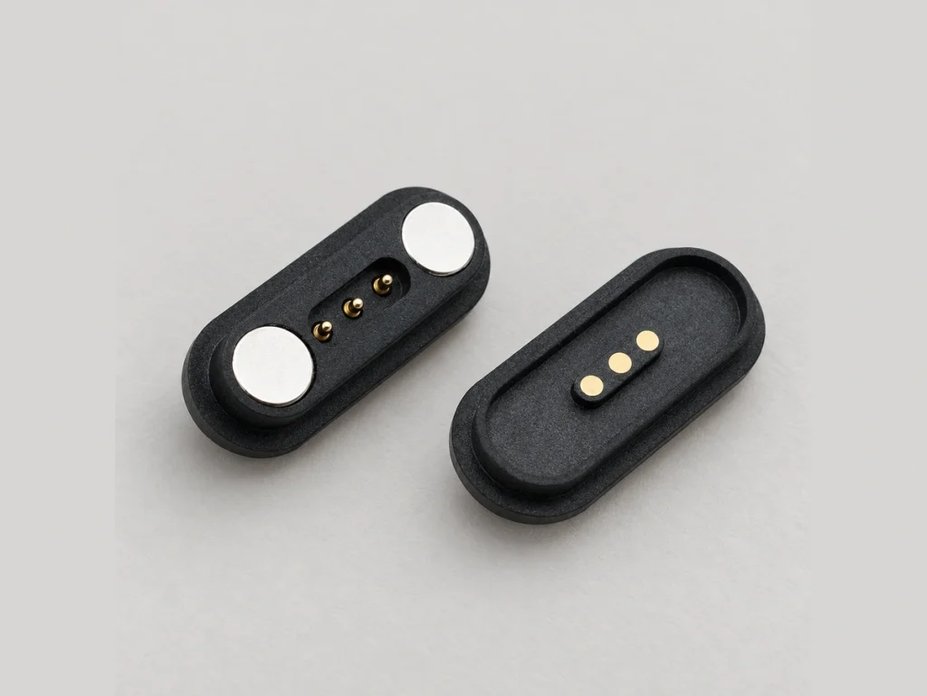
A compact magnetic interface for dependable power and data connections. Blind mating, repeated-use durability and custom configurations address the needs of demanding operating environments.
Stable 12V 3A power delivery for continuous connection
Rated for 10,000+ mating and unmating cycles
Corrosion-resistant construction tested with 48-hour salt spray
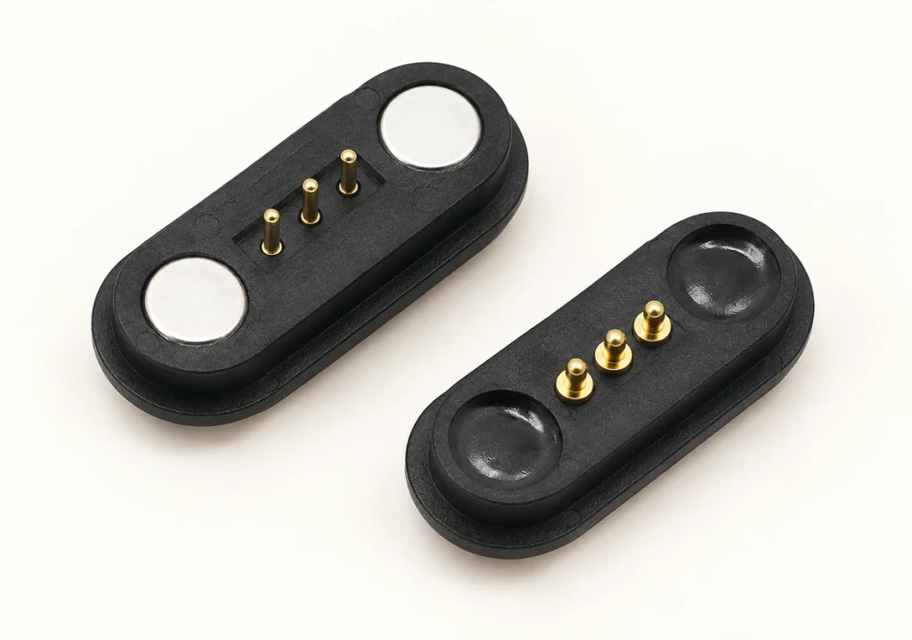
Keyed geometry guides the parts into the correct mating orientation
1 / 3
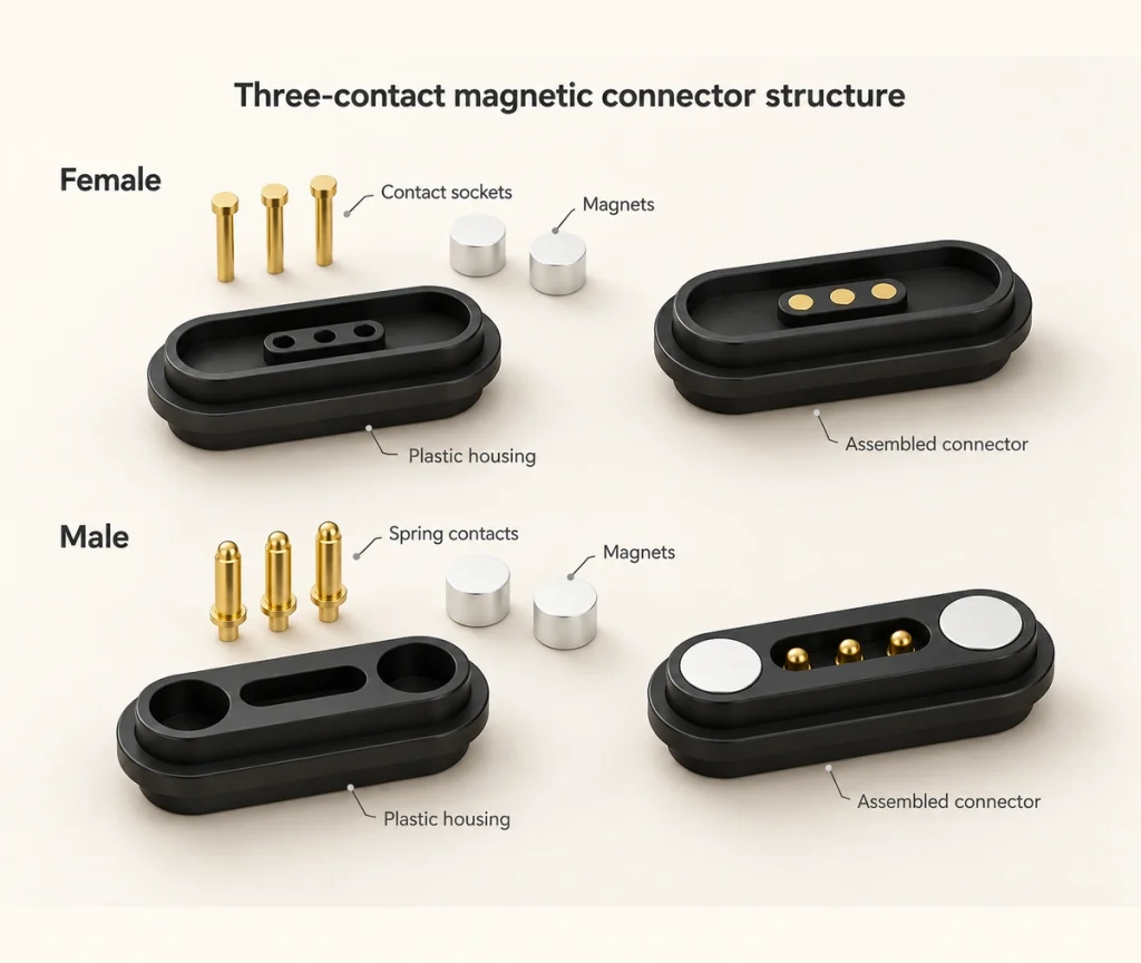
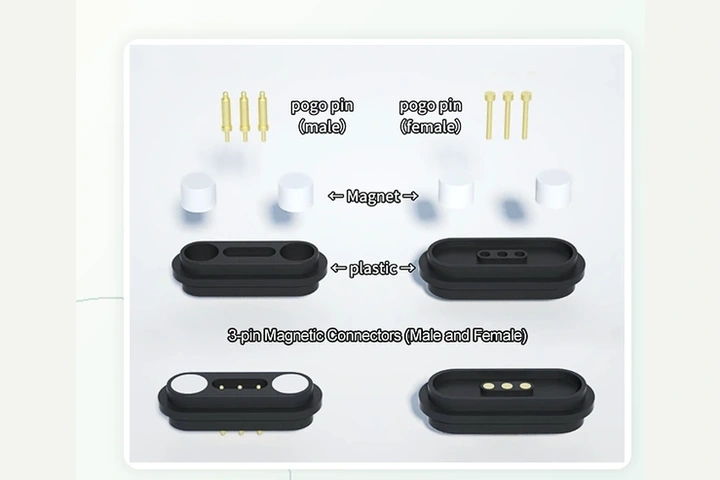
Inside the 3-Pin Connector: Structure and Specifications
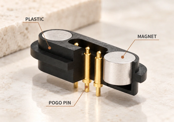
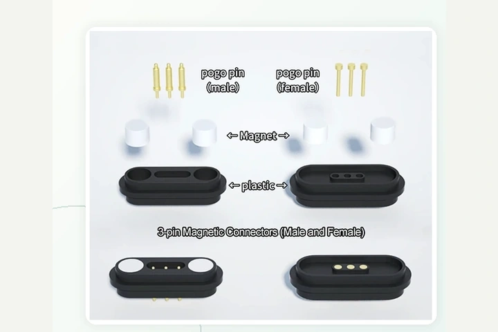
Precision-built magnetic pogo pin interface assembly
Quick Specifications
Designing a More Stable Docking Connection
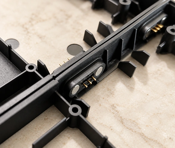
Conventional connectors can make docking awkward because the user must align the parts carefully. This 3-pin design combines magnetic guidance with mating geometry that resists misalignment, helping the contacts dock accurately and remain stable.
Magnetic Attachment
As the two mating parts approach, magnetic attraction draws them together automatically.
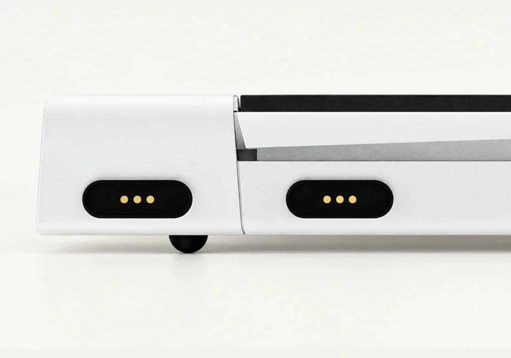
Built-in Magnet
The receptacle magnet sits within the plastic housing, which protects it against damage during magnetic attachment.
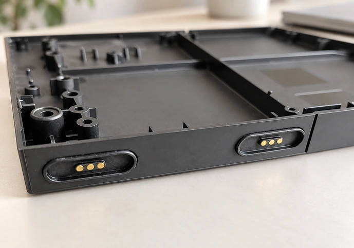
Foolproof Design
Matching recessed and raised housing features work with magnetic guidance to stabilize the docking position.
Waterproof Design
A recessed channel can hold environmentally friendly adhesive to improve the sealing of the magnetic interface.
Core Design Advantages
Three design features address common connection problems: easy alignment, release under an unexpected pull and a small footprint for the power and data interface.
Instant Blind Mating
N52 neodymium magnets align the parts without requiring the user to see the interface.
Fail-Safe Breakaway
The interface can separate when the cable is suddenly pulled, helping protect connected equipment from damage.
Space-Optimized Footprint
Three contacts provide power and a single data channel in a compact arrangement that uses little PCB space.
Video material pending replacement

17 YRS
Experience
3-Pin Connector Development and Manufacturing
Magtor manages 3-pin magnetic connector development from the first concept through high-volume production. Direct manufacturing brings design decisions, quality control and development timing into one process.
Precision Design
Our in-house engineers use CAD/CAM tools to design components to the required tolerances.
Prototyping & Molds
Prototype tooling and in-house mold making help move the design through development more quickly.
Custom Solutions
Pin positions, magnetic force and housing materials can be specified for the device.
Technical Support
A dedicated field application engineering team supports integration and testing.
Specialized Factory
Specialist manufacturing of 3-pin magnetic connectors

At the Connector Exhibition
Three visitors at a connector exhibition display.

Production Line
Controlled production with professional oversight

Quality Control
Quality checks using dedicated test instruments

Exhibition Visitors
Three visitors photographed at a connector exhibition.
Management Systems and Certificate Documents

ISO 9001

ISO 14001
QC080000
Supporting More Than 500 Enterprises Worldwide










1 / 10
Frequently Asked Questions
Can three contacts carry both power and data?
Can the sealing be adapted for outdoor use?
When can a custom prototype be ready?
What design measures reduce short-circuit risk?
Design Considerations
How Is a 3-Pin Magnetic Interface Constructed?
Permanent magnets, usually neodymium-iron-boron, align and retain the two parts of a contact-based 3-pin interface. One side has three spring-loaded pins, and the other has three copper contacts. Electrical transfer occurs where those contacts meet.
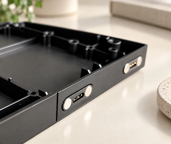
The interface connects quickly and can release readily. It suits charging and basic data applications where conventional USB or barrel connectors are difficult to align, vulnerable to damage or insufficiently protected.
Practical Benefits of a 3-Pin Design
Repeated-use durability Magnetic pogo pin designs can offer long service life. A separate design claim lists more than 100,000 mating cycles; applicability to this configuration remains to be confirmed against its 10,000+ cycle specification.
Protection during an accidental pull If a cable is caught or tripped over, the magnetic interface can release, helping prevent the cable from dragging the device.
Application-specific corrosion protection Coating materials can be selected to match the environment and the corrosion resistance required by the application.
Planning the Contact Assignment
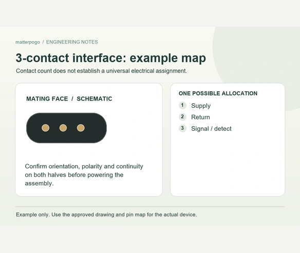
Assign the contacts around the actual circuit and safety requirements. The arrangement below is a proposed layout, rather than a universal 3-pin standard. Contact sequencing and short-circuit performance must be checked for the selected design.
Pin 1 (edge): GND — intended as the ground contact. Any ground-first sequencing and associated ESD benefit require confirmation from contact geometry.
Pin 2 (center): signal/data or detection — the central position can separate it from power contacts where the layout permits.
Pin 3 (edge): VCC — placed away from GND to address the risk of cross-contact during temporary misalignment.
Start a Custom Connector Project
Share the electrical, mechanical and environmental requirements of your device with Magtor. Our engineering team aims to return a tailored connection proposal and quotation within 24 hours.
Direct Email
Phone / WhatsApp
Headquarters & Factory
406, Building 3, No. 12, Zhenyuan Road, Wusha, Chang'an Town, Dongguan City, Guangdong Province, China