
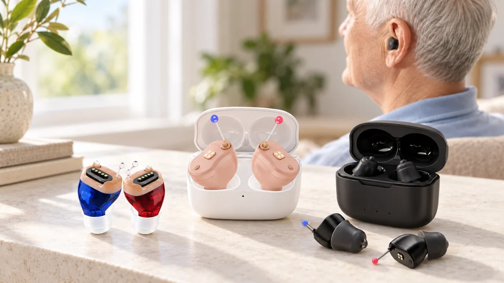
Magnetic Spring-contact Interfaces for Hearing-aid Charging
Evaluate custom four-contact and five-contact arrangements for charging docks, compact housings and magnet-guided spring contacts.
Hearing-aid charging cases can have tight space and docking requirements. Magtor can assess four-contact and five-contact magnetic arrangements against the housing and case layout. Define supply, return, detection and recognition paths with the circuit design, then evaluate contact engagement and retention for daily docking; contact count alone does not establish those functions.
Compact Four-contact and Five-contact Charging Interfaces
A hearing aid and its case need an interface that fits the enclosure and can withstand repeated attachment. Magnetic guidance and spring contacts can assist positioning inside the designed capture range, while case geometry and contact travel establish seating. Verify the complete arrangement for the intended users and docking conditions.
Compact packaging for the available space.
Magnet-guided attachment within the designed range.
A connector envelope matched to the enclosure.
Charging and supported data functions, subject to circuit and interface verification.
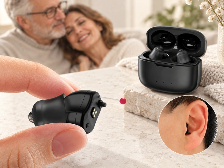
Four-contact and Five-contact Options
Choose the contact allocation from the required power and signals, then compare it with the available space.
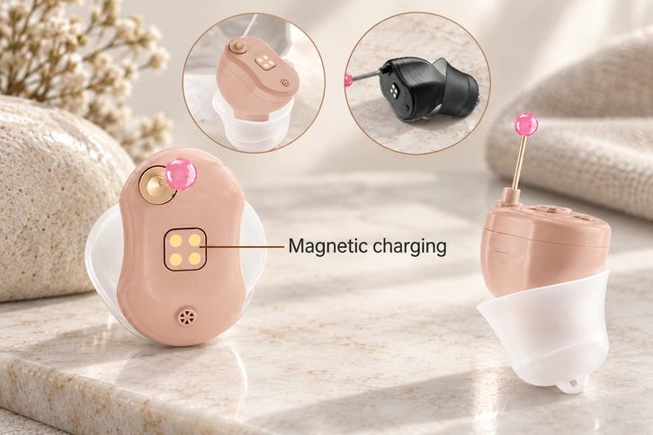
Four-contact Magnetic Interface for Hearing Aids
Candidate use: a charging interface with basic detection requirements.
Possible allocation: supply, return, detection and an additional supported signal within a compact mating arrangement.
Custom checks: working height, contact pitch and magnetic retention.
Potential benefit: guided docking and less forced-insertion wear when the charging case and locating features are suitably designed.
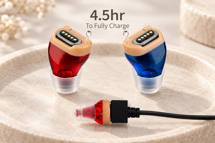
Five-contact Magnetic Interface for Hearing Aids
Candidate use: charging with additional data, identification or control paths.
Structure example: 5PIN M/F 1.50PH; confirm the pitch definition and dimensions on the selected drawing.
Custom checks: an extra path for device recognition or firmware-related functions where the circuitry requires it.
Candidate applications: advanced charging cases, small medical electronics and wearable modules requiring supported data synchronization; suitability requires device-specific qualification.
Connector and Cable Configurations to Evaluate
The following configurations are evaluation references. Confirm the selected model’s dimensions, current rating and media-to-part association before specification.
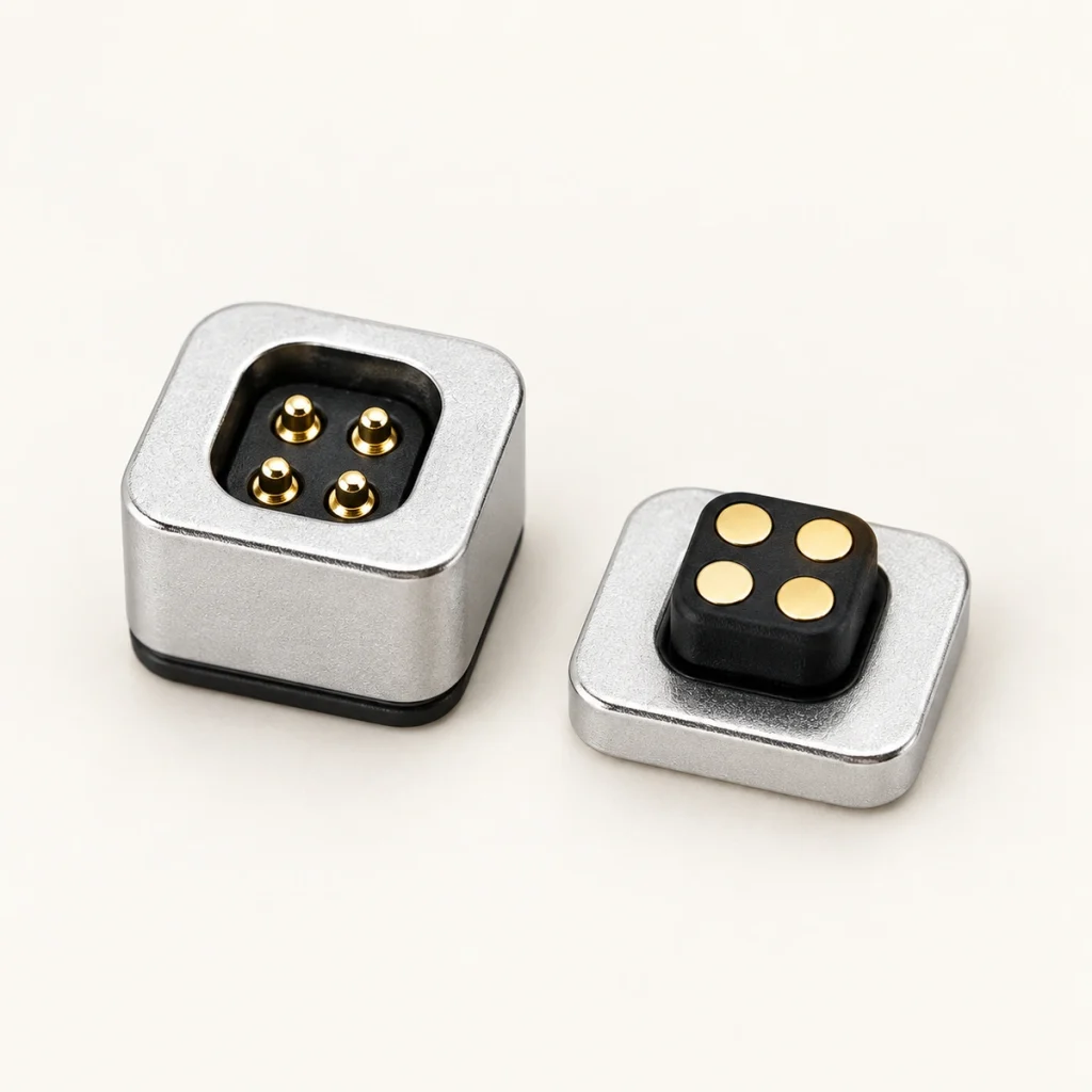
Four-contact magnetic connector
Part reference: 903-00006
Pitch notation: 1.30PH
Structure: male/female connector
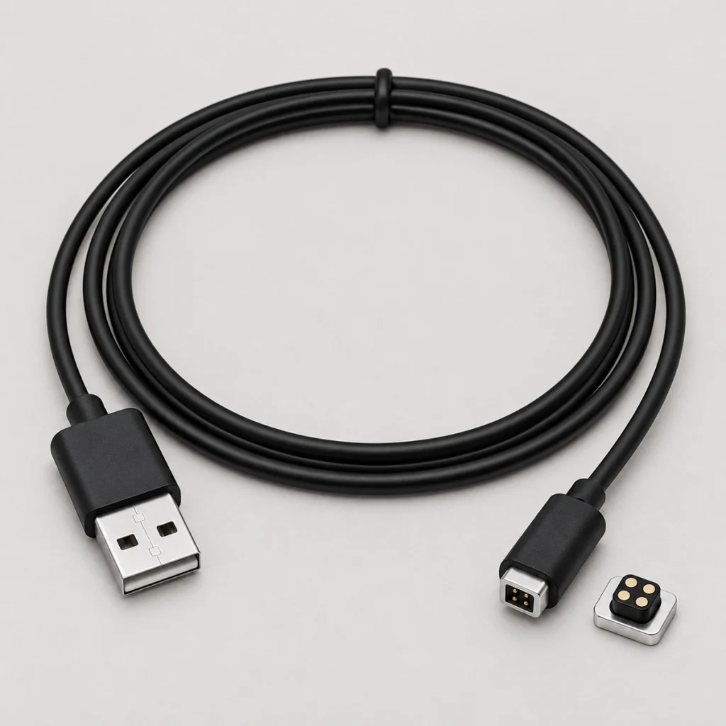
Four-contact magnetic cable
Part reference: 901-00008
Pitch notation: 1.30PH
Structure: cable assembly
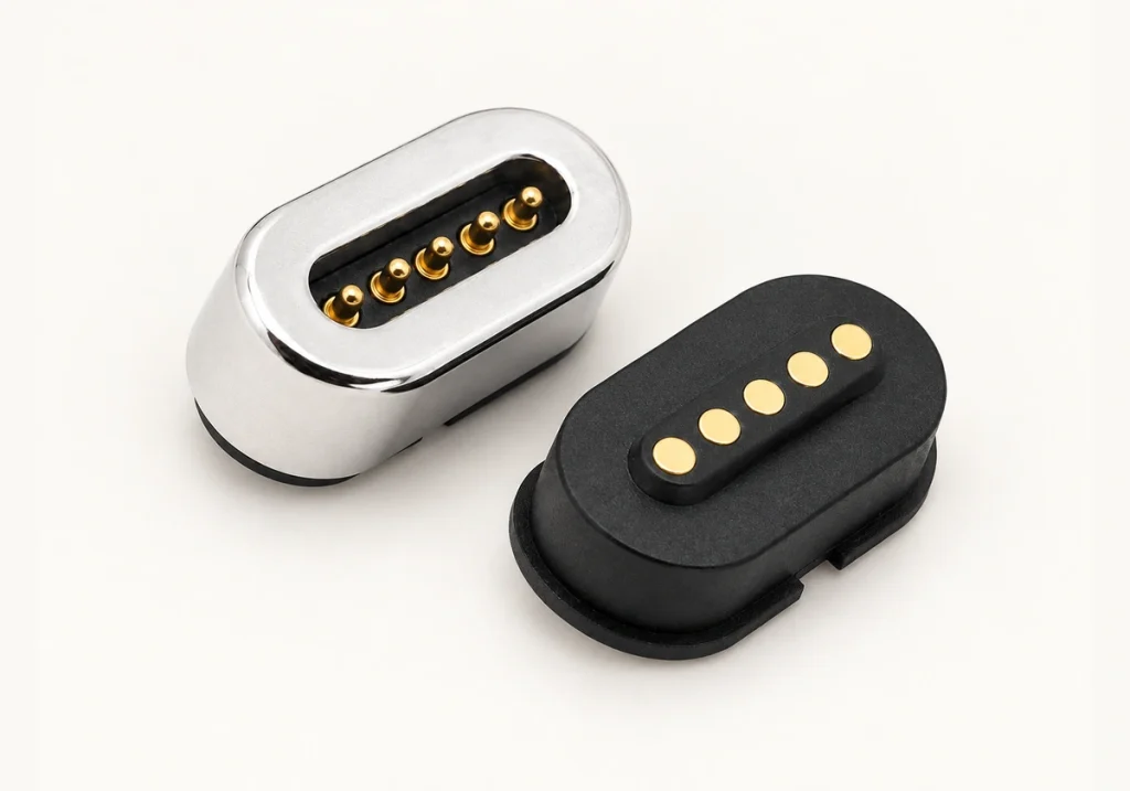
Five-contact magnetic connector
Part reference: 904-00030
Pitch notation: 1.50PH
Structure: male/female connector
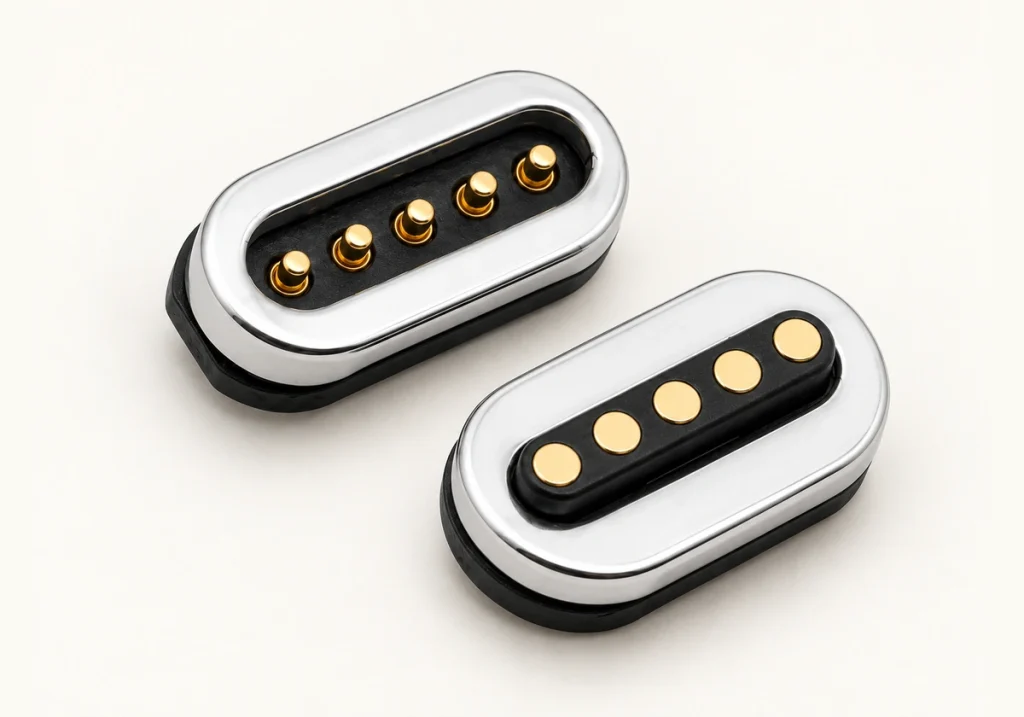
Five-contact connector arrangement
Part reference: 904-00032
Pitch notation: 1.50PH
Structure: male/female connector
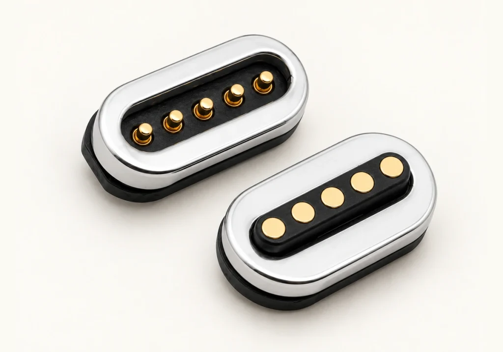
Five-contact magnetic interface
Part reference: 903-00031
Pitch notation: 1.50PH
Structure: male/female connector
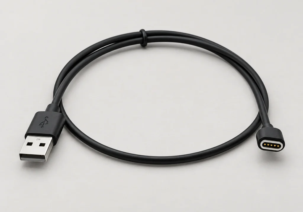
Five-contact magnetic cable
Part reference: 901-00010
Pitch notation: 1.50PH
Structure: cable assembly
Comparing Four and Five Contacts for Hearing-aid Charging
Use this structural and functional comparison alongside the actual PCB layout and circuit requirements.
| Comparison item | Four-contact magnetic connector | Five-contact magnetic interface |
|---|---|---|
| Example functions | Supply, return and basic detection, with allocation defined by the circuit | Supply, return and supported data, identification or control paths |
| Contact-allocation flexibility | A defined allocation for the required power and supported functions | One additional contact compared with a four-contact arrangement |
| Housing space | A compact option where the actual dimensions fit | May need more space; 5PIN M/F 1.50PH is one structure example |
| Charging-case integration | Assess the fit for the selected BTE or RIC dock | Plan the PCB pads and contact positions for the selected structure |
| Detection and identification | Basic presence detection is one possible assignment, not the only allowed function | Additional identification paths may be implemented with compatible circuitry |
| Charging arrangements | Charging case or magnetic cable, as defined for the product | Charging case or magnetic cable, as defined for the product |
| Candidate use | A compact charging design with the required basic paths. | A design needing an additional identification, data or control path. |
Scroll horizontally to view every column.
Options for Different Hearing-aid Structures
Assess these interface approaches against the project stage, enclosure and electrical requirements.
A. Charging Interfaces for BTE and RIC Devices
Project example: behind-the-ear or receiver-in-canal hearing aids.
Constraint: a restricted enclosure and charging-case envelope.
Candidate: a four-contact magnetic assembly.
Design goal: provide the required charging and detection paths within the available footprint.
View the OptionB. Charging Cases with Data or Identification
Project example: a smart case requiring a device handshake.
Constraint: enough separate paths for the implemented logic.
Candidate: a five-contact magnetic assembly.
Design goal: implement device recognition, battery-status detection or an additional data path where the electrical assignment supports it.
View the OptionC. Contacts Exposed to Sweat or Moisture
Project example: an interface exposed to skin, sweat and cleaning agents.
Constraint: exposure may cause corrosion or increased contact resistance.
Candidate: a custom sealed magnetic assembly with appropriate contact materials.
Design goal: assess sealing and plating together with the required salt-spray and actual chemical-exposure tests; a seal alone does not establish corrosion resistance.
View the OptionD. Cables and Test-fixture Interfaces
Project example: development jigs, external charging cables or sample tests.
Constraint: a removable connection suitable for repeatable validation.
Candidate: a five-contact magnetic cable arrangement.
Design goal: support a test fixture, programming dock or charging-case prototype cable with the required pin assignment and circuitry.
View the OptionWhy the Interface May Need Custom Development
Define the housing, exposure and user-handling requirements before choosing a hearing-aid charging interface.
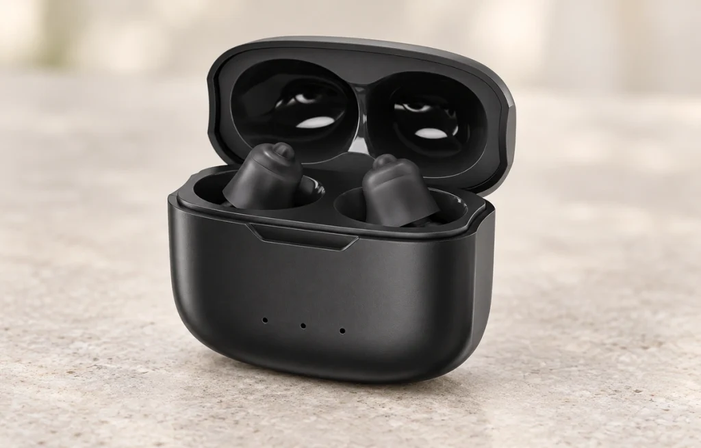
A. Restricted Housing Space
Project example: BTE, RIC, ITE or compact cases where the selected USB or USB Type-C interface does not fit.
Design constraint: the original example describes sub-millimeter space around PCB features and mounting holes; confirm the actual drawing dimensions rather than treating that as the connector size.
Approach: evaluate four or five contacts using the enclosure drawing, specified pitch and working height.
Design goal: fit the interface while retaining the required power and detection paths.
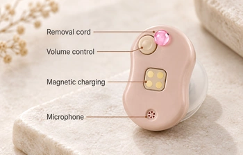
B. Daily Docking and Alignment
Project example: a case used daily by elderly or hearing-impaired users.
Design constraint: a small plug can require careful positioning, and forced insertion may damage the interface.
Approach: magnetic guidance assists the mating halves within the capture range, with locating geometry controlling seating.
Design goal: reduce incorrect-mating damage; any effect on field returns requires product-specific evidence.

C. Sweat, Moisture and Corrosion
Project example: daily exposure to sweat, moisture, skin oils and cleaning residues near the skin.
Design constraint: unsuitable contact materials or finishes may corrode and increase resistance; the rate depends on the actual exposure.
Approach: review plating, salt-spray tests, controlled temperature-and-humidity tests and the sealing structure, adding actual sweat or cleaning-agent exposure checks as required.
Design goal: maintain acceptable charging-path resistance after the qualified exposure, without assuming a fixed reduction in failures.
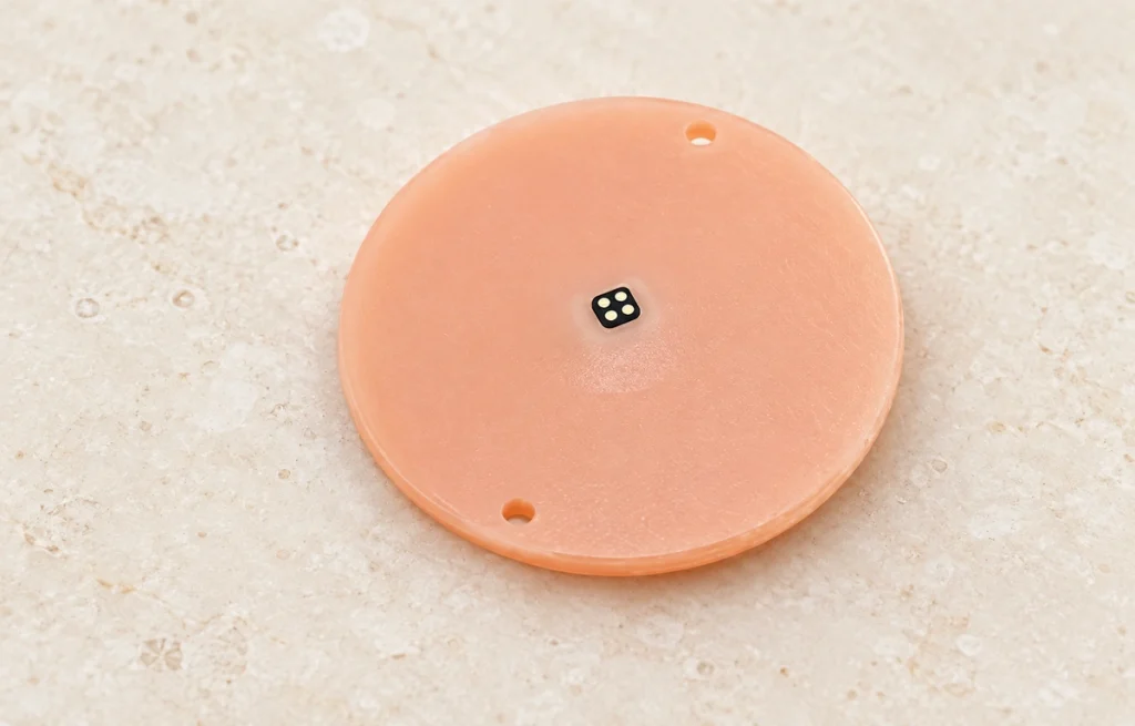
D. Power and Signals in One Interface
Project example: several functions must share a restricted mating area.
Design constraint: separate power and data connectors may not fit the selected enclosure.
Approach: a four-contact allocation can provide supply, return and supported detection or signals; a fifth contact adds a path where identification, data or control requires it.
Design goal: combine the required charging and recognition functions in a defined compact contact allocation.
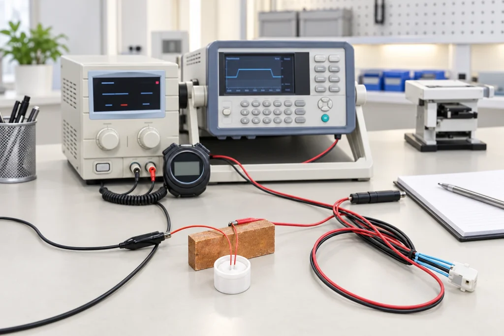
Assessing Contact Durability Under Exposure and Docking
Sweat, moisture, skin oils and cleaning residues can affect exposed charging contacts. Evaluate how the actual exposure and repeated docking change resistance, contact finish and engagement over time; these changes may contribute to charging problems.
Magtor can assess gold or composite contact finishes together with thickness, contact geometry and sealing before sample approval. Available test methods to discuss include plating-thickness inspection, salt-spray exposure, controlled temperature and humidity, mating-life tests and microscope inspection. Define resistance checks before and after exposure in the agreed validation plan; this is not a claim that this specific configuration has already passed those tests.
Manufacturing and Engineering Team
Discuss the production and inspection requirements with Magtor, including the evidence needed to confirm suitability for the selected configuration.
The company information lists ISO 9001, ISO 14001 and IECQ QC 080000 systems; current documents for the new entity must be supplied before publishing a valid certificate. A batch inspection plan may include contact height, resistance, magnetic polarity, plating thickness, visual dimensions, cable continuity and mating force. Agree which parameters are measured in-house or externally; do not infer that outside testing is never required.
Equipment described for project evaluation includes a 2.5D measuring instrument, CCD inspection machine, automatic resistance tester, plating-thickness tester, RoHS spectroscopy instrument, riveting machine, high- and low-temperature test equipment, salt-spray tester, life tester and mating-force tester. Confirm availability and the applicable method for the planned work.




1 / 4
Relationships with 500+ Enterprises Worldwide










1 / 10
Quality Systems and Certificate Documents

ISO 9001 — current new-entity document pending

ISO 14001 — current new-entity document pending

IECQ QC 080000 — current new-entity document pending
Engineering Questions for Hearing-aid Interfaces
Review these requirements before fixing the PCB pads or charging-case geometry.
Which Interface Can Be Considered for Hearing-aid Charging?
Why Consider Magnetic Spring Contacts for Hearing Aids?
How Should Four and Five Contacts Be Compared?
Can Five Contacts Carry Charging and Signals?
How Can Corrosion Risks Be Assessed?
What Information Is Needed for a Custom Interface?
Can the Assembly Fit a Small Charging Case?
Which Tests Should Be Agreed Before Production?
Can the Interface Be Designed for Sweat or Moisture?
What Does Magnetic Guidance Do for Docking?
Share Your Hearing-aid Interface Requirements
Provide the hearing-aid type, charging-case drawing or housing 3D file, and available contact space for an engineering assessment.
Contact assignment and current requirements.
Signal, recognition or detection functions.
PCB layout and mounting holes.
Water-protection and sweat-exposure requirements.
Required sample quantity and expected production volume.