
Six or Eight Magnetic Contacts: Circuit and PCB Selection
Published on October 6, 2026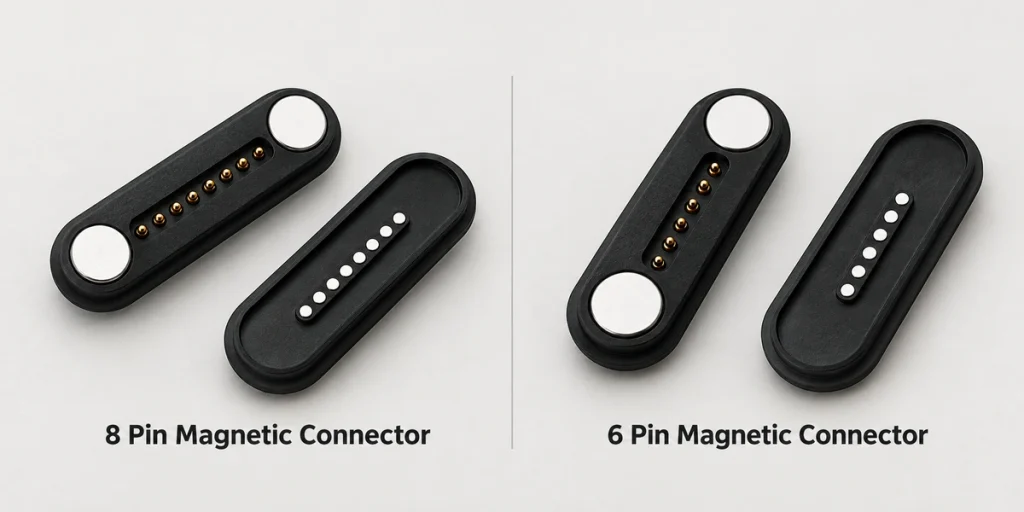
- What Two Additional Contacts Change
- Preparing the Contact Allocation
- Power and Data Design Conditions
- Footprint and PCB Integration
- When Six or Eight Contacts Fit
- OEM Selection Inputs
Six contacts may cover power, return, data and basic identification. Eight provide two more positions for signals, detection or controls. Choose between them using the actual assignment, current, PCB space, dimensions and device functions rather than contact count alone.
What Two Additional Contacts Change
The physical difference is six versus eight contact positions. Either architecture can allocate its positions to power, ground, data, identification, sensing or control according to the device circuit.
6 pin magnetic connector8 pin magnetic connectorThese custom magnetic pogo mates have no universal pinout comparable to a standardized connector interface. One six-contact map might use two power, two ground and two signal contacts; another might allocate power, data, ID and detection differently.
The extra two positions in an eight-contact design create allocation options. Their functions still need to be agreed during connector and PCB design.
PCB| Design Factor | Six-Contact Magnetic Interface | Eight-Contact Magnetic Interface |
|---|---|---|
| Contact positions | 6 | 8 |
| Basic charging | Possible within the assembly's electrical limits | Possible within the assembly's electrical limits |
| Power and data | Possible with a suitable complete circuit and signal path | Possible with a suitable complete circuit and signal path |
| ID or detection | Positions can be allocated as needed | Two additional positions expand allocation options |
| Multiple signals | Limited by the assigned six positions | Extra positions may accommodate more signals |
| PCB routing | May involve fewer routes for comparable functions | Additional active paths may increase routing work |
| Footprint | May use less contact space at comparable pitch | May need more contact space at comparable pitch |
| Custom assignment | Device-specific allocation is possible | Device-specific allocation is possible |
| Example use | Charging, data and identification as assigned | Additional power, data or control functions as assigned |
Scroll horizontally to view every column.
For an OEM project, begin with electrical functions and the complete interface requirements before deciding the contact count.
Preparing the Contact Allocation
Create a contact-allocation table before choosing six or eight positions. Count the paths needed for power, ground, communication, identification, sensors and auxiliary controls, including any parallel or shared paths in the architecture.
A hypothetical six-contact map could be:
Pin 1: Power
Pin 2: Power
Pin 3: Ground
Pin 4: Ground
Pin 5: Data
Pin 6: Data
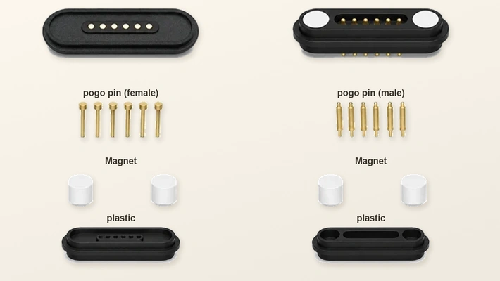
Another six-contact map could use one power, one ground, two data, one ID and one detection contact. Both examples fit six positions; their different assignments show why the actual map must be specified.
Eight positions may accommodate an additional power circuit, device detection, charge status, accessory ID or separate controls. A design could allocate several contacts to power and return while using the remaining paths for communication and control.
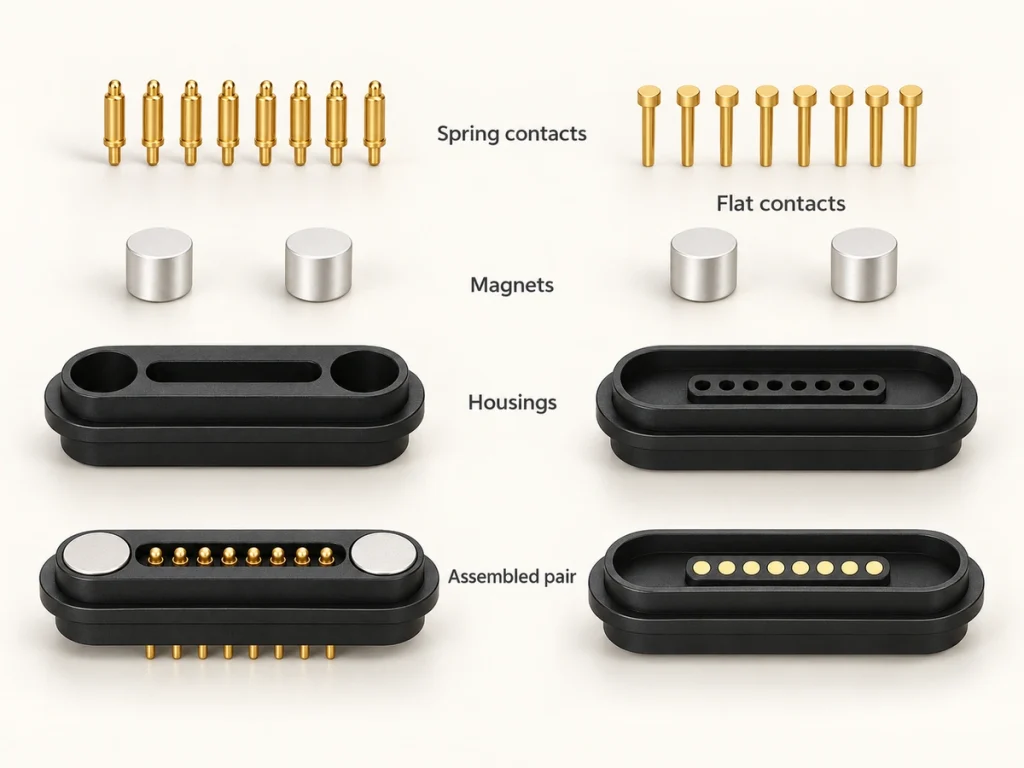
Define contact sequencing and electrical safety before fixing the layout. Some designs need ground or detection to engage before selected power or signal paths. Magnetic capture alone does not establish safe hot-plug behavior.
pin assignmentPower and Data Design Conditions
Either count may carry power and data when pogo pins, mating contacts, cable and PCB are designed for the required load and signal path.
Current capacity depends on pin diameter, resistance, spring force, plating, wire gauge, PCB trace design and operating temperature. Six or eight positions alone cannot set an allowable current.
Parallel contacts can sometimes distribute a higher-current load. For example, two positive and two ground contacts could leave other positions for data or controls. Verify current sharing, resistance and temperature rise; do not assume equal sharing or multiply a single-contact rating by contact count.
Eight positions may be useful when one interface needs several function groups, such as:
Power, ground, data, identification, detection and control.
Six contacts may already cover a charging and data interface. Eight become useful when the architecture needs additional paths beyond that allocation.
If only two power paths and two signal paths are required, eight positions may add contacts, conductors and PCB routes without a present function. Any reserved paths should have an explicit product-design reason.
Footprint and PCB Integration
Additional contacts can require more layout space. Eight need not be much larger if pitch, pin diameter and housing are changed, but greater density brings mechanical and electrical constraints that must be checked.
For compact wearables, handhelds and small charging modules, available PCB space may govern the choice. Six contacts could allow a shorter row or wider pitch while still meeting the required functions.
Where space and circuit needs justify eight contacts, review these ten mechanical inputs:
Contact pitch
Pogo-pin diameter
Working stroke
Spring force
Magnet location
Housing wall thickness
PCB mounting area
Cable exit direction
Alignment features
Sealing area
Reducing pitch may shrink the footprint while making manufacturing tolerance, alignment accuracy and PCB routing more demanding. Evaluate those effects together.
Review connector dimensions with the PCB and enclosure so that the selected footprint can actually be mounted, routed and mated.
When Six or Eight Contacts Fit
Six positions can provide a simpler allocation when they already cover the required power, signal and identification paths. This is a structural choice, not a claim of higher energy efficiency.
Six-contact design may suit these five needs:
Charging with basic data communication
Power, ground, ID and detection
A compact magnetic dock
Fewer cable conductors
Reduced PCB routing complexity where the circuit permits
Consider eight positions when additional channels are needed now or defined future functions require reserved contacts.
Possible eight-contact requirements include:
Power with multiple data paths
Additional ID or accessory detection
Separate control signals
Multiple sensing circuits
Several power or ground contacts
A more complex docking station
A multifunction charging interface
A wearable needing charging, two-way communication and identification might use six contacts. A medical, industrial or smart device combining charging, data, accessory detection and control might use eight. The device class alone does not determine the map or qualification.
Use the actual path budget and defined reserved functions to choose the count. Additional positions should solve a specific requirement.
OEM Selection Inputs
Document electrical and mechanical requirements before selecting six or eight contacts. This gives the allocation decision a clear engineering basis.
Prepare the following five groups of information:
Electrical: operating voltage, maximum current, power-path count, signal types, data requirements and any identification or control functions.
Mechanical: available dimensions, pitch, PCB mounting method, mating direction and cable exit orientation.
Environmental: moisture, sweat, dust, corrosion exposure, operating temperature and required sealing level.
Cable: USB-A, USB-C, bare-wire or terminal ends, plus length and wire gauge. Apply standardized requirements where relevant to the USB side; its end type does not establish the magnetic-side protocol.
USB-CMating: magnetic retention, required cycles, working stroke and alignment tolerance.
When six positions cover the required paths, they may reduce conductors and routing. Eight can expand allocation when the device needs additional signals, identification or controls. Compare actual layouts before claiming either assembly is smaller or simpler.
Ask whether the extra two contacts resolve an identified electrical or product requirement.
For custom OEM design, coordinate the map, pogo size, plating, magnet arrangement, cable termination and housing around the device. Those six features can be reviewed together rather than selecting a fixed shape first.
Selection Summary
Choose from the actual circuits and reserved functions. Six contacts may cover power, data and basic ID; eight may add signals, detection or controls. Complete the review with current, PCB space, dimensions, cable design and environmental requirements before agreeing the assembly.