
3-Pin Magnetic Charging Cables for OEM Devices
When a device needs power, ground and one additional signal or detection contact, Magtor develops the full three-contact cable assembly around its requirements. Contact assignments, head geometry, cable length and USB-A, USB-C, terminal or bare-wire ends can be specified for the project.
Factory-direct manufacturing combines industry experience with advanced production lines.
Adapt contact assignments, connector shape and cable terminations to the device.
Develop power and signal paths for demanding environments, with performance verified for the configuration.
Engineering support covers rapid prototypes, tooling and production preparation.
- Home
- Magnetic Cable Connector
- 3 Pin Magnetic Charging Cable
3 Pin Magnetic Cable Options
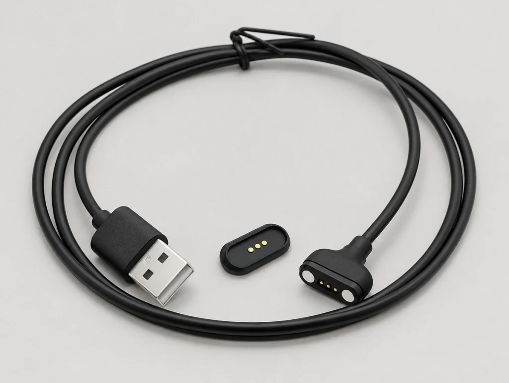
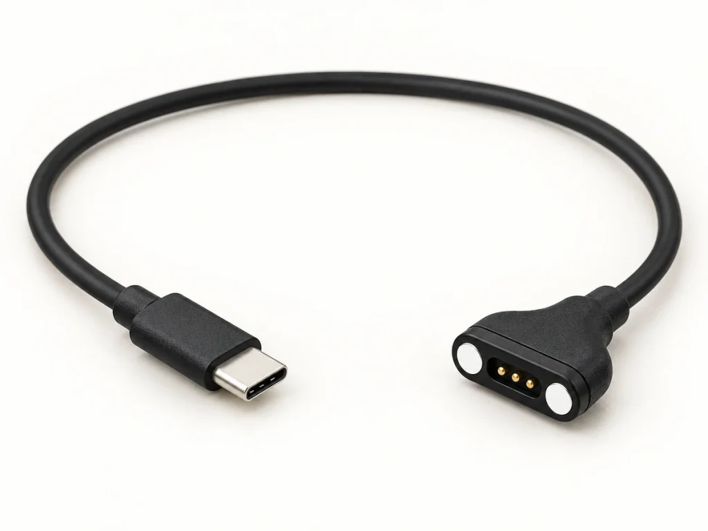
3 Pin Magnetic Charging Cable USB-A
The complete USB-A assembly suits consumer electronics, smart devices, charging docks and portable equipment needing a charging interface. Charging speed depends on the circuit and approved electrical design, rather than the USB-A end alone.
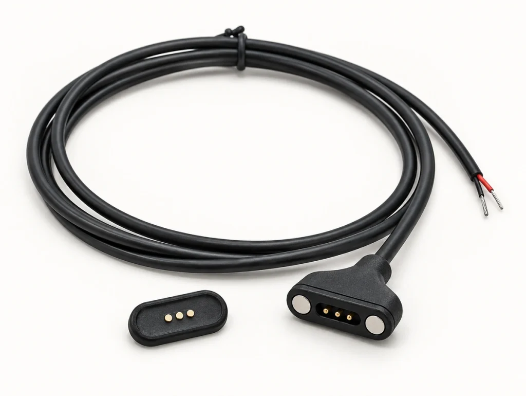
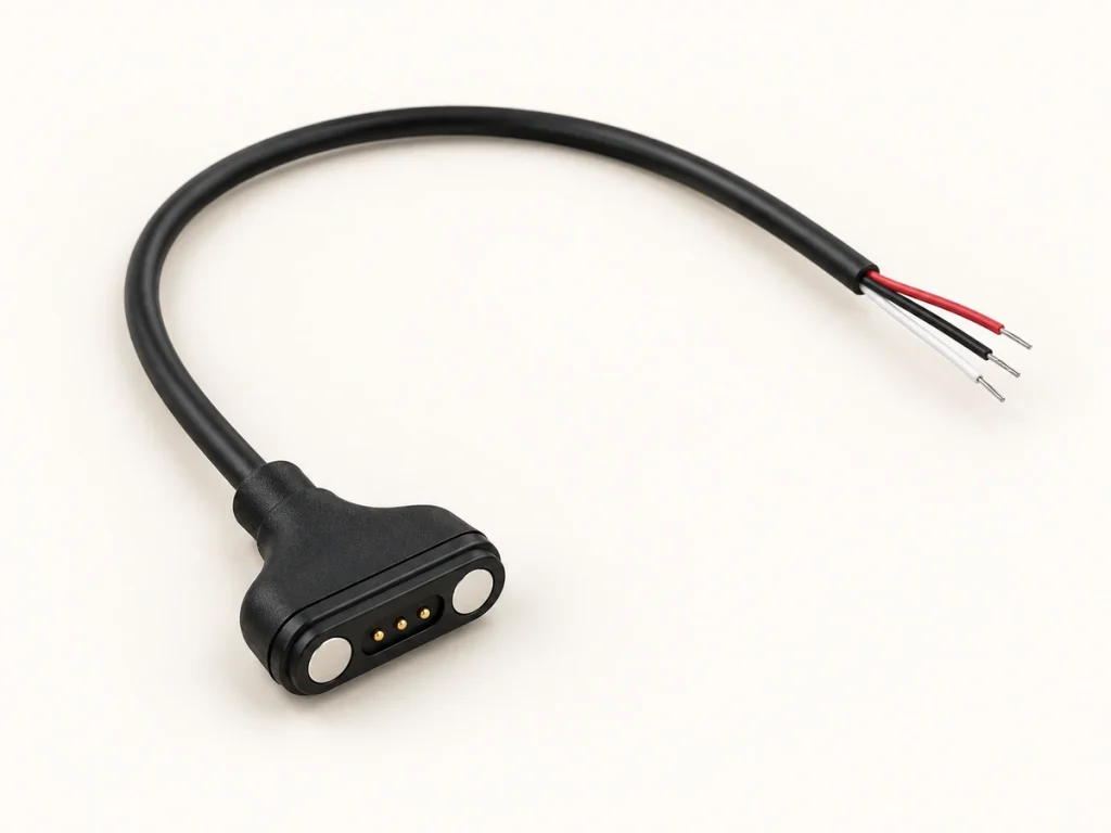
3 Pin Magnetic Connector Cable Open
An open-ended cable can be developed for customer-specific terminal integration and mating connectors.
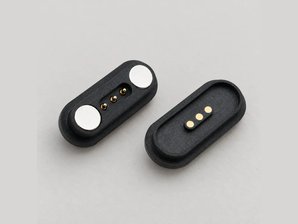
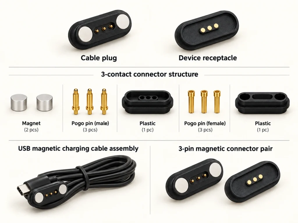
3 Pin Magnetic Connector
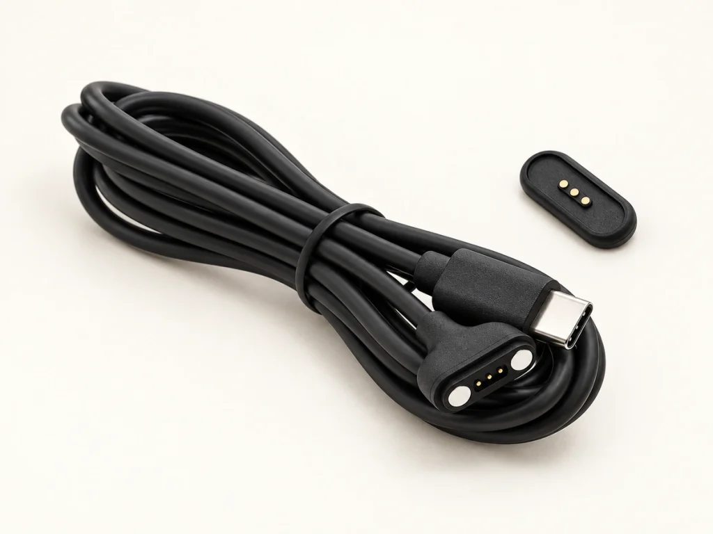
The matched device-side male and female parts use magnetic guidance and keyed geometry for rapid attachment. Rear sealing and custom protection ratings can be developed for the selected smart-device interface.
View 3 Pin ConnectorsExample 3 Pin Magnetic Cable Configuration
These specifications describe one example with a terminal/open end. Other models and project requirements can use different values.
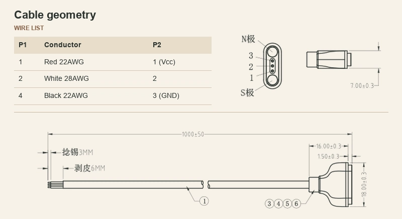
Reference Specifications
| Structure | 3 Pin Magnetic Head + Open |
|---|---|
| Voltage / Current | DC12V / 3A Max |
| Cable Length | 1000 mm |
| Wire | 28AWG × 1C |
| Jacket | Black TPE |
| Working Stroke | 1.00 mm |
| Mechanical Life | 10,000 cycles |
Scroll horizontally to view every column.
What Is a 3 Pin Magnetic Charging Cable?
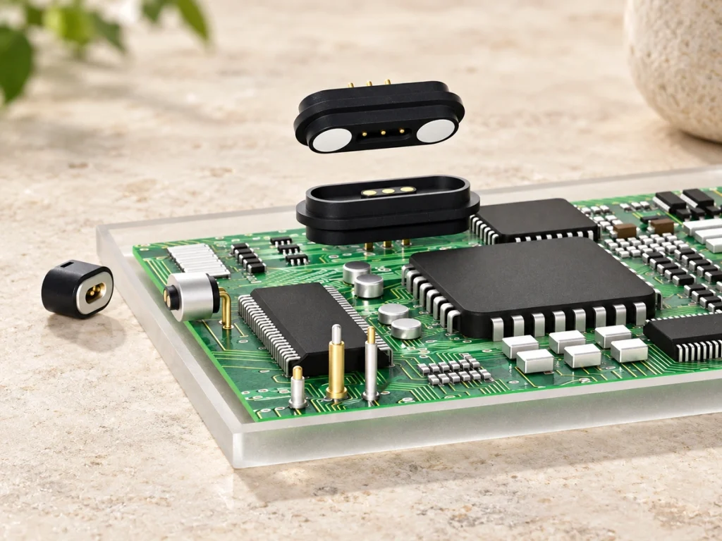
Built-in magnets align and retain the cable head. Three spring-loaded pogo contacts form its electrical interface.
The three contacts provide independent electrical paths between the source and device. A working system includes both the cable assembly and its matching device-side connector.
Three contacts do not define a universal pinout. Match the assignments to the approved OEM device schematic.
What Does the Third Pin Do?
The device schematic and approved contact map determine the role of the third contact. V+ and GND are typical power assignments; the remaining contact can serve one of the functions below.
Power + Ground + ID
ID: allow the charger or host to identify the connected hardware version.
Power + Ground + Detect
Detection: identify docking or attachment so software can change charging mode or display connection status.
Power + Ground + Control
Control: provide an enable or charging-control path for the battery management circuit.
Custom Development
Custom function: engineers define the three contacts around the device requirements.
How Do I Know If a 3 Pin Magnetic Charger Is Compatible?
Contact count is only one compatibility check. Different OEM devices do not share a universal three-contact charger standard.
Before specifying a replacement or custom cable, you must confirm:
Pin pitch (spacing)
Connector geometry & housing
Magnetic polarity (N/S)
Electrical polarity (+/-)
Pin assignment & function
Working height / compression
Voltage / Current rating
Device-side connector match
Choose the Cable End for Your Device
Select the end around the connection method used by the host system or power source for power and signals.
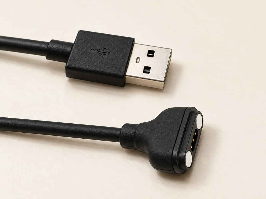
USB-A
For conventional USB supplies, charging adapters and standard accessories.
USB-C
For a USB-C power input; the connector does not by itself establish USB PD support.
Open Cable
Develop the required terminal arrangement around the equipment connection.
Custom 3 Pin Magnetic Charging Cable for OEM Devices
Once an enclosure, PCB and charging recess are fixed, a standard cable can have the wrong pitch, reversed polarity or an incompatible termination.
Magtor reviews the enclosure and PCBA drawings together. Mechanical dimensions and electrical paths can then be adapted to fit the recess and match the battery layout.
Customizable Parameters:
Connector dimensions
Pin pitch & assignment
Cable length & wire gauge
Cable OD & color
Overmolding design
Magnetic & electrical polarity
Cable outlet direction
USB / terminal / bare wire
What Should You Confirm Before Ordering?
Prepare these details for engineering review before approving the sample design.
| Parameter | Why It Matters | Information to Provide |
|---|---|---|
| Device Application | Select materials for the operating environment. | Device type, usage scenario. |
| Pin Assignment & 3rd Pin Function | Define the required paths, such as V+, GND and detection. | Wiring diagram or sequence. |
| Pin Pitch & Connector Dimensions | Match the connector to the mating geometry. | 2D/3D enclosure drawing. |
| Voltage & Current | Select conductor size and the internal contact structure. | Max voltage (V) and current (A). |
| Polarity (Magnetic & Electrical) | Check polarity and the intended mating direction to address short-circuit risk. | N/S magnet position, +/- pinout. |
| Cable Specs (Length, AWG, OD) | Plan flexibility, voltage drop and cable routing. | Length (mm), AWG size, OD limit. |
| Termination Type | Define the connection to the power source or PCB. | USB-A/C, specific terminal, or bare wire. |
| Device-side Connector | Match the opposing device-side magnetic interface. | Part number or drawing of mating part. |
Scroll horizontally to view every column.
Applications for 3 Pin Magnetic Charging Cables
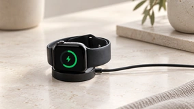
Smartwatches & Wearables
Design constraint: a small wearable housing needs charging plus detection or ID in a compact interface.
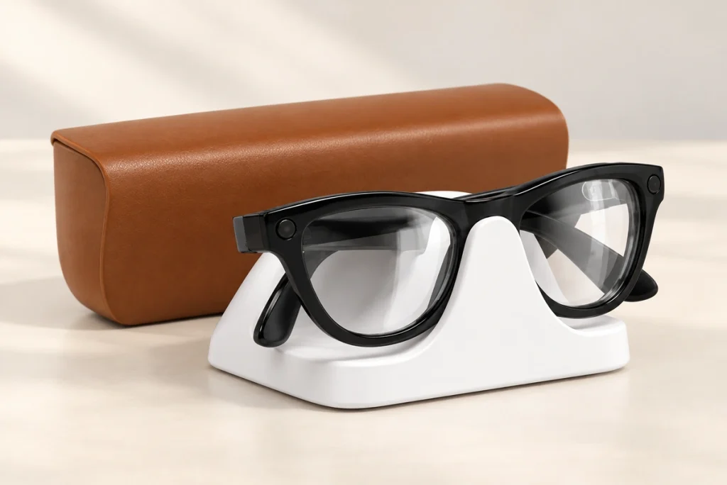
Smart Glasses
Design constraint: a thin wearable housing has little interface space. Design approach: a compact three-contact cable with a USB end.
Charging Docks
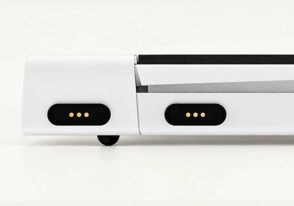
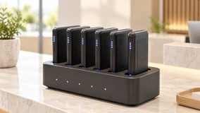
Design constraint: docking without visual alignment plus connection detection. Design approach: assign the third contact to detection or ID.
Handheld Electronics
Design constraint: portable terminals charge frequently and need service access. Design approach: use a replaceable external cable.

IoT Devices
Design constraint: a small sensor enclosure has limited space. Design approach: integrate terminal or bare-wire ends internally.

Medical Electronics
Design constraint: an interface that can be cleaned and connected repeatedly. Design approach: a custom three-contact connection for compact medical electronics, validated as part of the device.

3 Pin vs 2 Pin Magnetic Charging Cable
| Feature | 2 Pin | 3 Pin |
|---|---|---|
| Typical basic function | Power + Ground | Power + Ground + additional function |
| ID / Detection | Limited without extra contact | Can use third contact |
| Interface size | Can be smaller | Adds one electrical path |
| Typical use | Charging-only | Charging + ID / Detect / Control |
Scroll horizontally to view every column.
Choose contact count around the electrical functions the device needs. These examples are typical design choices, rather than universal contact standards.
Explore alternatives: 2 Pin Magnetic Charging Cable | Magnetic Cable Connector
2 Pin Magnetic Charging CableMagnetic Cable Connector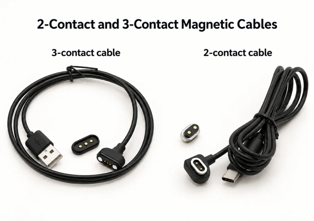

Testing and Manufacturing Support for OEM Cable Projects
After sample approval, batch consistency still needs inspection. Check conductor sequence, polarity, connector position, cable length and spring-contact performance during volume production.
Cable continuity / wire testing
Open / short verification
Contact resistance
Spring force
Plating thickness
Dimensional inspection
Mating-cycle testing
ROHS material checking
Management Systems and Certificate Documents

ISO 9001

ISO 14001

QC080000
Frequently Asked Questions
What is the third pin used for on a magnetic charging cable?
Are all 3 pin magnetic charging cables interchangeable?
Can a 3 pin magnetic charging cable support data?
Can a 3 pin magnetic cable use USB-C?
What is the difference between a terminal cable and bare-wire cable?
How do I measure the pin spacing on my existing charger?
Can Magtor match a three-contact cable from a drawing or sample?
What information is needed to customize a 3 pin magnetic charging cable?
Request a Custom Engineering Quote
Share your cable project with Magtor for engineering review. Our team evaluates the requirements for prototypes and production at scale.
Direct Contact
Email Address
Contact details to be suppliedPhone / WhatsApp
Contact details to be suppliedHeadquarters & Factory
406, Building 3, No. 12, Zhenyuan Road, Wusha, Chang'an Town, Dongguan City, Guangdong Province, China