
3-Pin Magnetic Charging Cables: Pin Functions, Compatibility and OEM Design
Published on September 28, 2026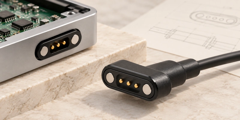
- Three-Contact Cable Structure and Operation
- Functions for the Additional Contact
- Signals and Data Requirements
- Electrical and Mechanical Specifications
- Checking Cable Compatibility
- Choosing Two, Three or Four Contacts
- Information for a Custom OEM Cable
A three-contact magnetic cable can combine charging with an additional ID, detection, control or signal path. This guide reviews pin allocation, data requirements, compatibility and the specifications needed for OEM selection.
3 pin magnetic charging cableThree-Contact Cable Structure and Operation
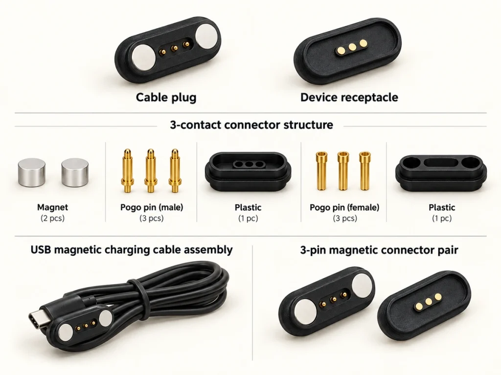
The assembly typically includes a cable, magnetic housing, three contacts, magnets and a device-side counterpart. Many OEM designs pair spring-loaded pins with flat mating pads.
magnetic connector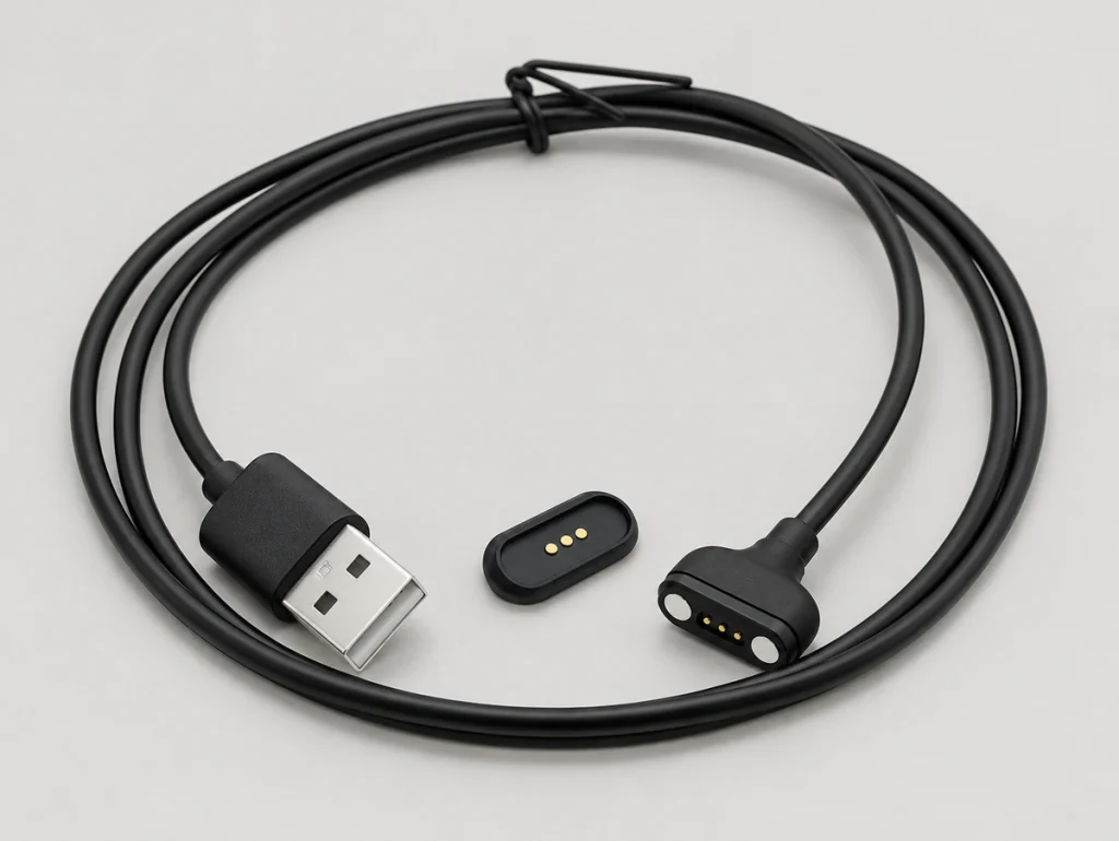
Magnets position and retain the halves while the pins compress against their pads to complete the electrical paths. One typical arrangement is:
Power source → cable → magnetic connector → pogo pins → device contacts → PCB / charging circuit.
Assign power, ground, ID, detection, control or another function according to the device circuit. Three contacts alone do not identify the pin map.
Equal contact counts do not establish compatibility between two cables.
Functions for the Additional Contact
Many designs use two contacts for power and ground and assign the remaining contact to another function. Its role must follow the device's electrical architecture.
Possible assignments include:
| Example Assignment | Possible Function |
|---|---|
| V+ / GND / Detect | Sense that the charger is connected |
| V+ / GND / ID | Identify a cable, accessory or device |
| V+ / GND / Control | Enable or control charging |
| Power / Signal / GND | Carry power and a project-specific signal |
Scroll horizontally to view every column.
A wearable might detect cable attachment through the third contact. Another device might identify an approved accessory before enabling its charging circuit.
The additional contact may also carry a simple control or communication signal if the circuit supports it. Pin 1, Pin 2 and Pin 3 have no universal assignments across magnetic cables.
Confirm the electrical pin map before finalizing the mechanical interface.
Signals and Data Requirements
A three-contact cable may provide a signal path, but that does not automatically create a conventional data interface.
For instance, the assignment:
V+ / GND / ID
might use its extra contact solely for accessory identification. Alternatively:
V+ / GND / Detect
might only report whether the cable is attached.
Assess useful data capability through:
Pin assignments
Device communication circuit
Signal type
Required data rate
- Contact resistance
Cable construction
Shielding requirements
Ground reference
Connector geometry
Low-speed ID or control and high-speed digital data have different requirements. Define the communication first, then check whether the available signal path is sufficient.
Several independent data paths alongside power and ground may justify four, five, six or more contacts, depending on the circuit.
Electrical and Mechanical Specifications
Contact count is one selection input. The cable needs to match electrical, mechanical and environmental requirements together.
Review these specifications:
| Specification | Design Relevance |
|---|---|
| Operating voltage | Match the charging architecture |
| Continuous current | Specify the contact and conductor load |
| Peak current | Assess short-duration electrical loading |
| Pin assignment | Define power, ground and the additional function |
| Contact pitch | Set mating spacing and interface width |
| Working stroke | Set compression and contact stability |
| Spring force | Determine pressure at the working position |
| Magnetic force | Balance retention and intended release |
| Connector dimensions | Fit the enclosure and installation space |
| Wire gauge | Assess current capacity and voltage drop |
| Cable length | Assess installation and electrical losses |
| Contact plating | Assess wear and corrosion requirements |
| Environmental protection | Address moisture, sweat and dust exposure |
| Mechanical life | Meet the repeated-mating requirement |
Scroll horizontally to view every column.
Available total travel is insufficient if the completed assembly leaves the pin outside its intended working-compression range.
Balance magnetic retention with the combined spring force of all three contacts. Normal mating needs adequate compression without an unnecessarily difficult release.
Specify USB-A, USB-C, bare-wire or terminal ends together with length, gauge, jacket material and strain relief. A USB-C end alone does not define data or charging-protocol capability.
USB-CChecking Cable Compatibility
Three matching contact positions in appearance are not a complete compatibility check.
Products with three contacts may differ in electrical polarity, contact functions, spacing, magnet position, housing geometry or charging voltage.
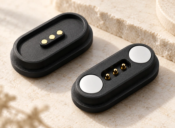
Before replacement or integration, confirm at least:
Connector length and width
Contact positions
Contact spacing
Pin or pad diameter
Electrical polarity
Pin assignments
Magnet positions
Magnetic polarity
Mating direction
Installed working height
Charging voltage
Current requirement
Housing keying or alignment features
Similar-looking heads may place V+ at different contacts. An unchecked pin map can leave the connection inoperative or damage the device.
Magnetic polarity can also prevent mating. Some designs use polarity or asymmetric housing features to discourage reversed attachment.
For OEM equipment, check the approved mechanical drawing and electrical pin map before judging the connection compatible.
Choosing Two, Three or Four Contacts
Determine contact count from the independent electrical paths required by the architecture.
| Contact Count | Example Allocation |
|---|---|
| 2 pins | Basic power and ground |
| 3 pins | Power, ground and one additional function |
| 4 pins | Power, ground and two additional functions |
Scroll horizontally to view every column.
Two contacts can be sufficient for an interface needing only DC power and ground.
2 pin magnetic charging cableA third path can serve detection, ID, control or a simple signal when one extra function is required.
Four contacts may suit two additional circuits or a design that cannot allocate power and signals reliably across three contacts.
4 pin magnetic charging cableAdding contacts can enlarge the head, constrain pitch, complicate PCB routing and increase the combined spring reaction. More contacts do not automatically make the interface better.
Let the circuit architecture determine the count.
Information for a Custom OEM Cable
Define electrical and mechanical requirements before sample design to make the development review more focused.
Provide these electrical inputs:
Operating voltage
Continuous current
Peak current
Pin map
Additional-contact function
Required signal characteristics
Provide these mechanical inputs:
Available connector dimensions
Device-side installation space
Mating direction
Contact pitch
Target magnetic holding force
PCB or housing position
Required mating cycles
For the cable, define:
Cable length
Wire gauge
Outer cable diameter
90° or 180° exit direction
USB-A, USB-C, bare-wire or terminal end
Strain-relief requirements
Environmental inputs can include sealing, sweat, humidity, temperature range, corrosion and repeated cleaning. Specify the conditions and acceptance criteria for each requirement.
waterproofingcorrosion resistanceA 2D drawing, 3D model, initial pin map, prototype quantity and estimated annual demand help assess whether to adapt an existing platform or develop a new structure.
Developing and Validating the Complete Interface
Coordinate pogo pins, magnetic force, housing geometry, cable, pads, electrical assignments and device structure as one interface.
Define each contact's function, check mechanical compatibility, select contact and magnetic parameters, then validate the assembly under the device's actual operating conditions.