
Eight-Contact Magnetic Interfaces for Power and Data
Published on October 7, 2026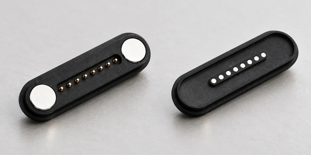
- How Power and Signals Cross the Interface
- Allocating Eight Contacts
- Designing the Communication Path
- Establishing Current Capacity
- Maintaining Contact Reliability
- When Additional Paths Are Useful
An eight-contact magnetic interface may carry power and data together when contacts, cable, PCB and assignments meet the required current and signal conditions. Positions can be allocated to power, ground, data, ID, detection or controls; eight contacts alone establish none of those ratings.
8 pin magnetic connectorHow Power and Signals Cross the Interface
A typical pogo-based mate combines magnetic guidance, spring-loaded pins and matching flat pads. Magnets position the halves, while the touching conductive contacts transfer current or signals between cable and device.
Each position provides a physical contact path that the circuit can use independently or connect in parallel. Some paths may serve power and return, with others serving data, ID or controls. Magnetic force provides positioning and retention in this architecture; it is not the means of electrical transfer.
Design the OEM interface with its pogo pins, mating pads, PCB traces, cable conductors and device circuitry. These five elements form one electrical system.
Allocating Eight Contacts
No universal map applies to every eight-contact magnetic mate. Define the positions for the actual device architecture.
The following simplified assignment is one example:
| Pin | Possible Function |
|---|---|
| Pin 1 | Power |
| Pin 2 | Power |
| Pin 3 | Ground |
| Pin 4 | Ground |
| Pin 5 | Data + |
| Pin 6 | Data − |
| Pin 7 | ID / Detection |
| Pin 8 | Control / Auxiliary Signal |
Scroll horizontally to view every column.
A different device may use one power and one ground contact, leaving more positions for communication, sensing or accessory detection. The table is an example, not an interchangeable connector standard.
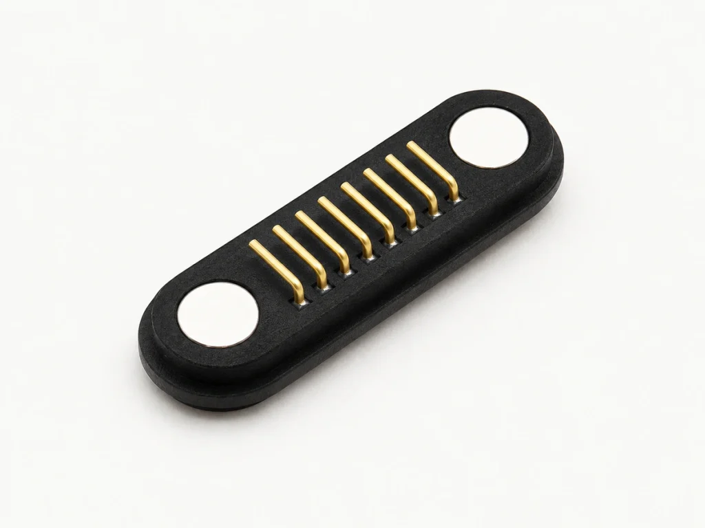
Agree the assignment before PCB and cable design. Conductor count, gauge, contact spacing and routing depend on that map.
Designing the Communication Path
Data transfer is possible in a suitable assembly, but achievable rate depends on the complete signal path rather than the eight-contact count.
Lower-speed ID, charge-status, sensor or control signals may be simpler to implement. Higher-speed differential links need attention to resistance, spacing, impedance, PCB routing, cable construction, shielding and electromagnetic interference. Assess all seven factors for the required interface.
contact resistanceelectromagnetic interference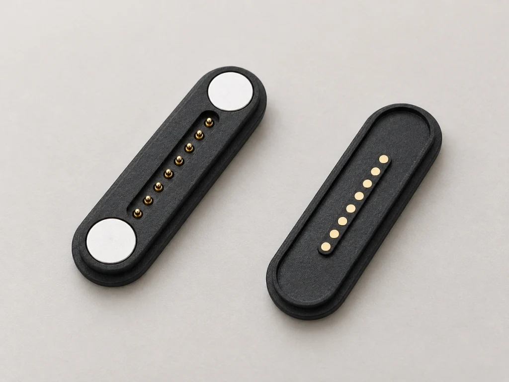
For USB or another defined protocol, design and validate the complete path at the required rate. Eight conductive positions do not automatically meet that protocol's requirements.
Where charging and basic communication need separate data, ID or control paths, additional positions may offer allocation flexibility. The required functions determine whether eight are useful.
Establishing Current Capacity
Current capacity comes from contact and assembly design. The fact that a mate has eight positions supplies no current, voltage or power rating.
Review these ten current-path inputs:
Pogo-pin diameter
Contact resistance
Spring force
Working stroke
Contact plating
Cable wire gauge
- PCB trace width
Number of power contacts
Operating temperature
Condition of the mating contacts
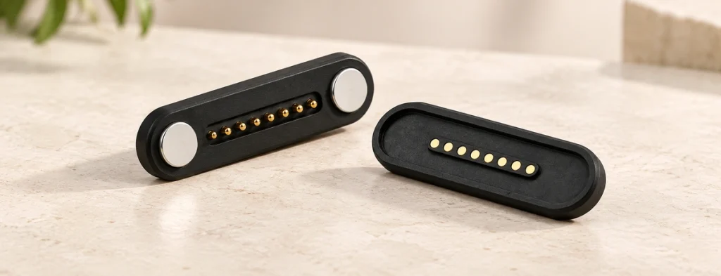
A higher-current design may parallel positive and ground contacts. One example uses two for power and two for ground, leaving the others for data or control. Define that arrangement as part of the complete circuit.
Parallel paths can distribute current, but sharing is not necessarily equal. Verify resistance and temperature rise across the assembled path before setting its allowable load.
Maintaining Contact Reliability
Stable power and signal transfer depends on the complete contact system, including how it mates and stays engaged.
Coordinate spring force and working stroke to maintain sufficient pressure throughout engagement. Too little compression may make resistance unstable; too much may increase mechanical stress and shorten contact life. Use the agreed working range rather than an unspecified maximum compression.
Evaluate mating surfaces and plating for repeated use and corrosion exposure. Gold finishes are an option, but sweat, moisture, dust and other contamination can still affect an exposed interface. Match housing protection and surface treatment to the intended environment.
Coordinate magnet arrangement, housing geometry and locating features so all eight contacts reach the intended repeatable position. Magnetic capture alone does not confirm that every contact has engaged correctly.
When Additional Paths Are Useful
Consider eight contacts when the device needs functions beyond a simple two-wire charging path.
Possible requirements include these seven groups:
Charging with data transfer
Power with device identification
Multiple power and ground contacts
Sensor or control signals
Accessory detection
Dock communication
Separate charging and signal circuits
One compact-device example allocates two contacts to power, two to ground, two to data and two to ID or controls. Eight physical positions can keep these function groups separately allocated within a single magnetic mate; the circuit determines any parallel connections.
Four or six contacts may suffice for charging with a few signals and may simplify the PCB or structure. Compare the actual layout and path budget. Additional positions should have a defined function or reservation reason rather than being selected solely for a higher count.
Design Summary
Power and data can share a suitable eight-contact interface. Review assignments, pogo structure, resistance, cable, PCB layout and signal requirements as one system. Positions may serve power, ground, data, ID, detection or control when a multifunction OEM device needs those additional paths.
magnetic connectorEngineering Questions
Does eight-contact mating establish water protection?
No. A sealed version may be developed, but its IP performance depends on housing, seal grooves, O-rings or adhesive, cable entry and the device enclosure. Define conditions and verify the complete assembly; contact count supplies no IP rating.
Can the assembly support higher-power charging?
It may, where pin diameter, resistance, wire gauge, PCB traces and the number of power contacts meet the required voltage and current. Evaluate charging protocols separately from the conductive path's capacity.
Can it be connected while power is active?
Only if the circuit and interface are designed for that use. Evaluate inrush current, contact sequencing, arcing risk and device protection before allowing repeated live attachment and removal.
How should service life be specified?
Set the required mating cycles and verify the actual assembly. Pogo structure, stroke, spring force, plating thickness, alignment and environmental exposure all influence durability; eight positions do not establish a lifetime.
Which cable ends can be used?
USB-C, bare-wire and terminal ends are possible OEM configurations when wiring and contact assignments match the device's electrical requirements. An end type alone does not establish USB capability on the magnetic side.
USB-C