
Eight-Contact Magnetic Mates and USB-C: OEM Interface Choices
Published on October 7, 2026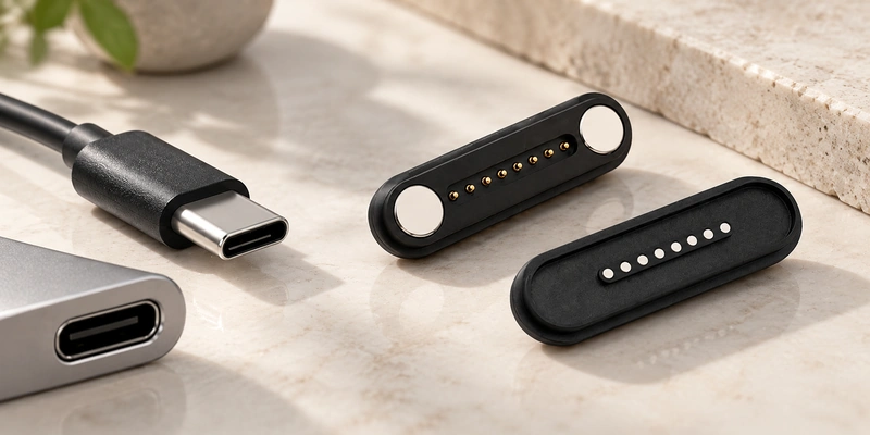
- Standardized and Device-Specific Interfaces
- Power and Data Implementation
- Mating and Docking Experience
- Sealing the Complete Device
- OEM Customization Options
- Choosing and Combining the Interfaces
An eight-contact magnetic mate may suit guided docking, designed breakaway and custom assignments. USB-C may suit standard cables, compatible chargers and implemented USB protocols. Compare power, data, enclosure and mating requirements to select or combine the interfaces.
Eight-Contact Magnetic InterfaceStandardized and Device-Specific Interfaces
Standardization is a central distinction between these architectures.
USB-C defines a connector system with mechanical and electrical requirements. Charging, data, Power Delivery and other functions depend on the device, cable and controllers implementing the relevant USB specifications; the connector shape alone guarantees none of them.
Native USB-C Interface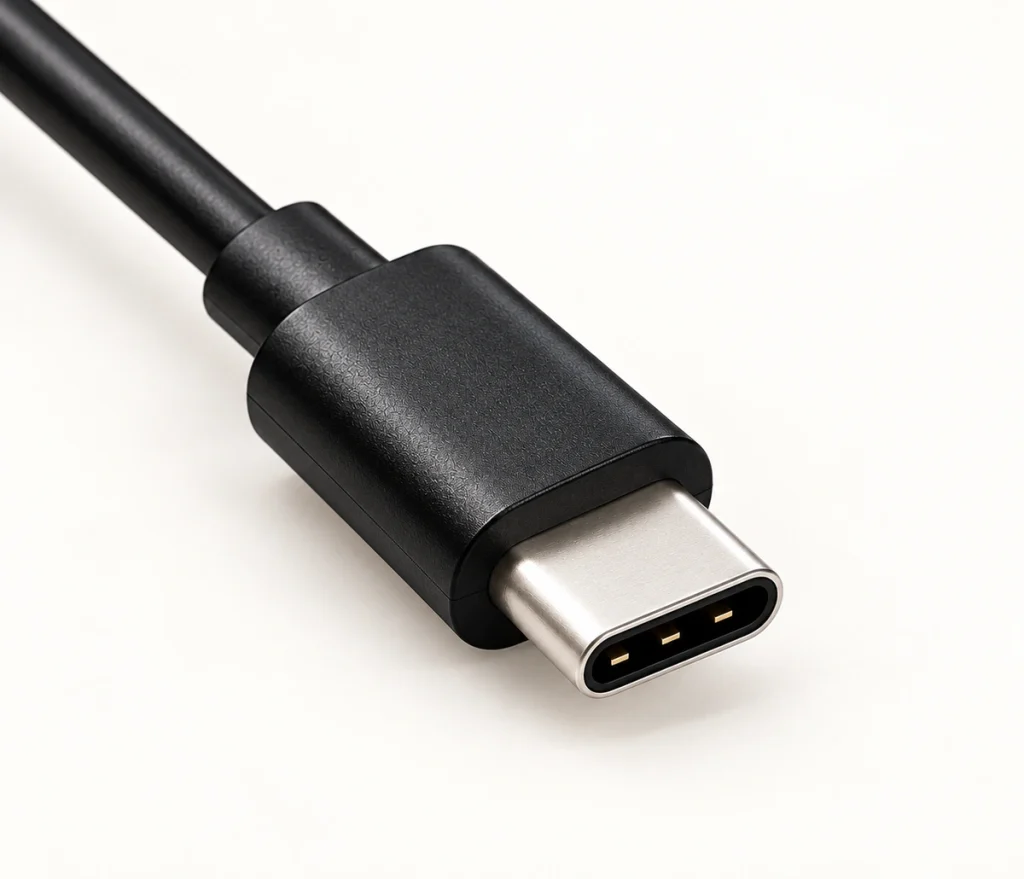
A custom eight-contact mate can define its own assignments and coordinate housing, magnets, pogo pins, cable exit, mating force and mounting with the device. These six design features remain subject to engineering and manufacturing review.
The resulting options address different design priorities, as the comparison below shows.
| Design Factor | Eight-Contact Magnetic Interface | Native USB-C Interface |
|---|---|---|
| Standardized mate | Typically device- or supplier-specific in this comparison | Defined Type-C connector architecture |
| Custom contact assignment | Defined for the device | Must respect the standard interface architecture |
| Automatic alignment | Possible through magnetic and mechanical guidance | Not inherent in an unassisted native plug |
| Blind mating | Possible with suitable guiding geometry | Requires insertion alignment unless added guidance is provided |
| Breakaway | Can be designed for a specified release force | Not an inherent feature of a standard plug |
| Compatibility | Requires a matched mechanical and electrical mate | Broader standard ecosystem; functions still must match |
| Housing geometry | Can be developed around the device | The mating interface dimensions are constrained |
| Power and data | Possible with a suitable complete path | Possible with the implemented cable, device and protocols |
| Frequent docking | May suit a validated docking design | Depends on the port, dock and use conditions |
Scroll horizontally to view every column.
USB-C can provide a useful standard ecosystem when consumer cables and accessories must interoperate. A dedicated OEM magnetic mate can allow more device-specific mechanical integration where a matched interface is acceptable.
Power and Data Implementation
Either architecture may transfer power and data when its complete implementation supports the required functions.
USB-C implementations can support USB data, charging and higher-power operation through Power Delivery where the relevant functions are implemented. Check device, charger, host, accessory and cable capabilities for the intended use; standard form does not make all combinations equivalent.
Implemented USB Power DeliveryCustom magnetic pogo interfaces generally need a device-specific map. An eight-contact design could assign its positions to the following functions:
Power
Ground
Data +
Data −
ID
Detection
Control
Auxiliary signal
Such allocation can be useful when the device needs additional functions alongside charging and communication.
Contact count sets neither data rate nor current capacity. Resistance, pin diameter, spring force, cable construction, PCB routing and signal integrity all affect performance and require review for the proposed assembly.
Contact resistanceFor higher-speed data, validate the whole transmission path at the required rate. A custom magnetic mate does not inherit USB-C capabilities, and USB-C capabilities themselves depend on the implemented protocol and cable.
Mating and Docking Experience
Magnetic guidance offers mechanical design options that may be useful for handling and docking.
magnetic connectorsMagnetic capture can guide the halves into position and reduce the precision needed to insert a conventional plug. Suitable geometry may make one-handed or blind docking easier, while the conductive contacts still need to engage correctly.
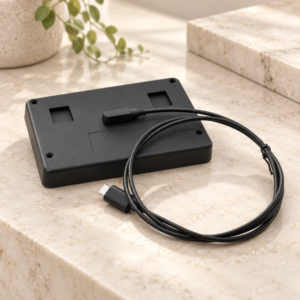
A specified magnetic release force may let the mate separate under a pull. For wearables, handhelds or charging docks, that behavior can reduce enclosure or cable stress, depending on geometry and retention. It does not guarantee protection from every pull.
Native USB-C uses a plug inserted into a receptacle. Its reversible orientation helps handling, but mating still involves physical insertion.
For repeated daily docking, designers may look for these five features:
Guided automatic alignment
Short mating travel
Blind docking with suitable locating features
Reduced insertion effort
Defined magnetic retention
Those features may matter for charging docks, wearables, smart devices and equipment returned frequently to a charging station.
USB-C may be preferable when users need standard cables and chargers, with the supported functions checked for those combinations.
Sealing the Complete Device
Water protection depends on the complete mechanical assembly and installation, whatever the connector type.
A USB-C receptacle creates an enclosure opening that needs sealing around the connector body, PCB interface and housing. Sealed components are available, but their protection must be integrated and verified within the device enclosure.
Surface mating contacts can offer a different enclosure arrangement. A custom magnetic design may avoid a deep plug cavity, subject to its locating, sealing and protection requirements.
Possible sealing and environmental-protection measures include:
O-rings
Seal grooves
Adhesive sealing
Potting
Molded protective housing structures
Sealed cable entry
Contact plating selected for corrosion exposure
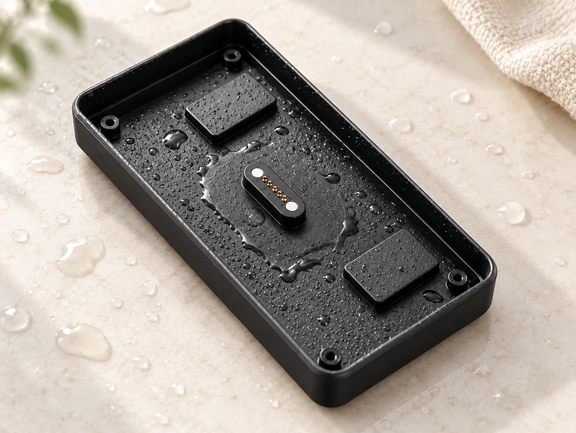
A suitably protected surface interface may be useful in wearable or outdoor devices exposed to moisture or sweat. Define those environments independently rather than treating them as one water-rating requirement.
Exposed contacts still need corrosion, contamination and long-term exposure evaluation. Describe a magnetic assembly as waterproof only when its complete design and testing support the stated protection conditions; this architecture supplies no automatic rating.
OEM Customization Options
USB-C's standardized mechanical and electrical ecosystem supports interoperability while setting design constraints. Keep the standardized mate within its defined architecture when integrating it.
A matched custom magnetic interface allows a different set of device-specific choices.
custom magnetic connectorEngineering review can cover these thirteen features:
Contact count
Contact pitch
Pogo-pin size
Working stroke
Spring force
Magnet arrangement
Housing dimensions
PCB mounting method
Cable length
Wire gauge
USB-C cable end
Bare-wire cable end
Terminal connection
Set the contact map around the product circuit and document it with the mating assembly. A custom assignment still needs agreement and verification before use.
For example, a device may need separate charging, communication, accessory-detection and identification circuits. Eight positions can provide allocation options for those four function groups when the circuit requires them.
A custom pogo mate may be useful when the interface is integrated into the product's mechanical design and docking behavior, as well as its electrical connection.
Choosing and Combining the Interfaces
Make the decision from the device requirements and supported external ecosystem.
Consider USB-C when these six priorities apply:
Compatibility with suitable standard cables
Interoperability with supported devices
Implemented standardized high-speed protocols
Implemented USB Power Delivery
Access to compatible third-party chargers
A familiar consumer connection
Consider a custom magnetic pogo mate for these eight priorities:
Magnetic alignment
Blind mating with suitable guidance
Frequent docking
Designed breakaway behavior
Device-specific assignments
Compact surface contacts
A dedicated charging interface
Device-specific mechanical integration
The interfaces can coexist. A cable may use a magnetic mate at the device and USB-C at the power-source end, with the entire assembly designed for the intended electrical functions.
That arrangement can combine custom docking with compatible power adapters. Match the source, cable, magnetic contacts and device circuitry before relying on charging or Power Delivery behavior.
Selection Summary
USB-C may suit standardization, interoperability and established protocols when the relevant capabilities are implemented. An eight-contact magnetic design may suit alignment, repeated docking, designed release, custom circuits or mechanical integration. Compare electrical load, data, enclosure, environment and daily connection behavior to choose the architecture.
Engineering Questions
How does service life compare with USB-C?
Compare the actual assemblies at the required mating cycles. Pogo structure, stroke, spring force, plating, alignment and environment affect life. Avoiding conventional plug insertion does not by itself prove longer service life.
Can the magnetic design help avoid reverse polarity?
Mechanical keying and magnet-polarity design can guide mating toward the intended orientation. Verify the behavior and consider electrical reverse-polarity protection in the circuit; guidance alone is not a universal guarantee.
Could nearby electronics be affected by magnets?
Assess magnet strength, separation and sensor position for compasses, Hall sensors and other field-sensitive components. The effect depends on the particular device and layout; no universal safe spacing is established here.
How do development costs differ?
USB-C can use established standard components. A custom magnetic interface may need tooling, mechanical development, assignment definition and validation, increasing initial work and cost, especially at low volume. Confirm the project scope before comparing prices.
What maintenance should be considered?
Keep exposed contacts free of dust, oil, moisture and other contamination that can raise resistance. For wearable or outdoor use, specify plating, sealing and manufacturer-approved cleaning requirements during design.