
Custom 4-Pin Magnetic Charging Cables
Magtor develops four-contact magnetic cables for OEM charging, power and optional signals. The circuit and interface requirements determine what each contact does; there is no fixed four-contact assignment.
- Custom development: choose pitch, cable direction and termination.
- 3A / Pin: available on the applicable listed configurations.
- 10,000+ Cycles: intended for repeated magnetic docking.
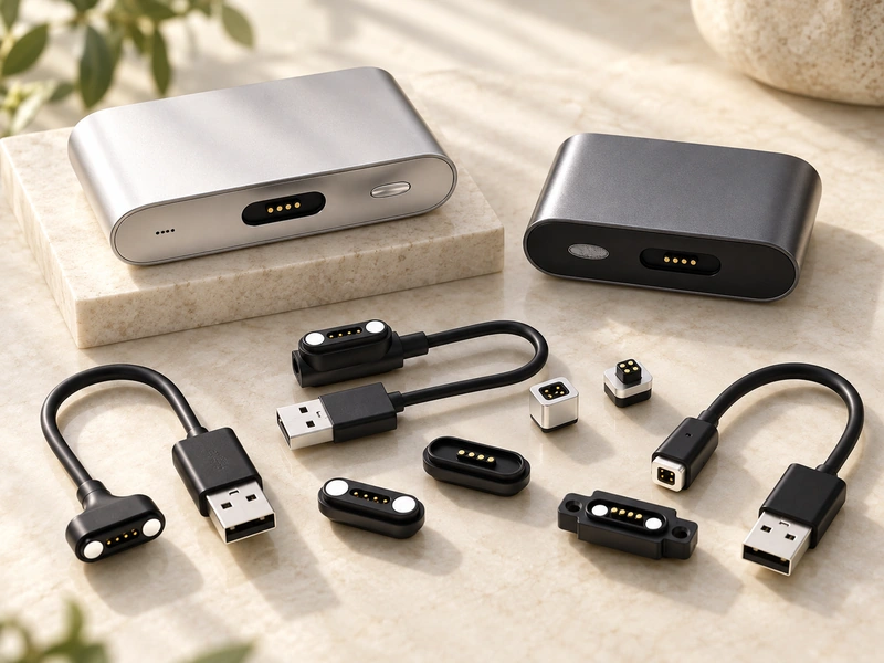
4 Pin Magnetic Cable Options
Select the wiring and connector arrangement around the enclosure and internal PCB. Custom development can address a configuration that is not covered by the standard options.
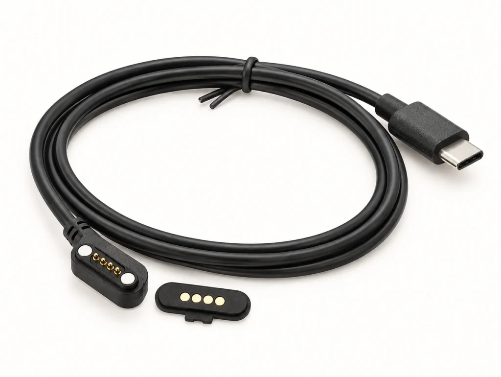
4 Pin Magnetic Charging Cable
Pitch 2.50mm
Current Rating 2A / Pin
Life test 10000+
Magnets N52 NdFeB
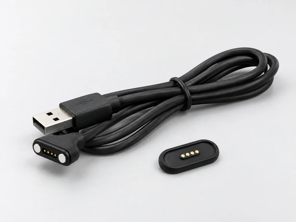
4 Pin Magnetic Cable 180° / 90°
Pitch 2.00mm
Current Rating 3A / Pin
Life test 10000+
Cable Outlet 180° / 90°
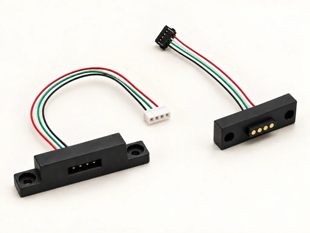
4 Pin Magnetic Cable Bare Wire
Pitch 2.00mm
Current Rating 3A / Pin
Life test 10000+
End Type Custom
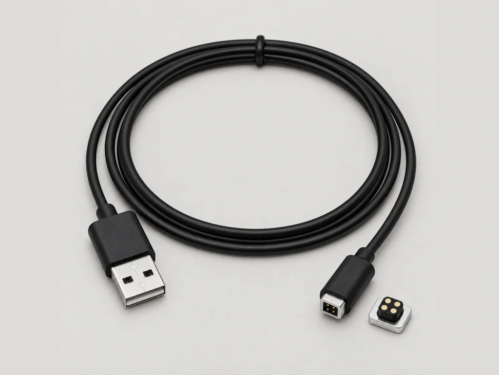
Square 4 Pin Magnetic Charging Cable
Pitch 1.30mm
Current Rating 2A / Pin
Life test 10000+
Magnets N52 NdFeB
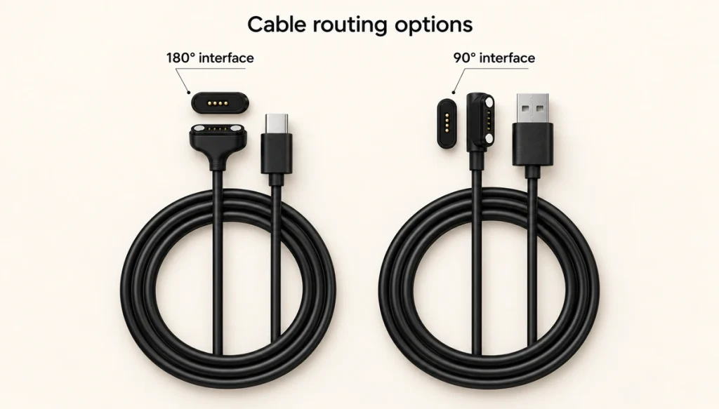
90° vs 180° Magnetic Connector Cable
A battery, PCB or housing wall behind the charging port can make a 90° side outlet useful. If the rear area is open, a 180° outlet provides a straightforward cable path.
| Item | 90° Cable | 180° Cable |
|---|---|---|
| Cable direction | Side / angled | Straight back |
| Rear clearance | Lower requirement | More space required |
| Cable routing | Side routing | Straight routing |
| Typical design | Thin housing / dock | Open rear space |
| Selection basis | Housing + PCB layout | Direct cable path |
Scroll horizontally to view every column.
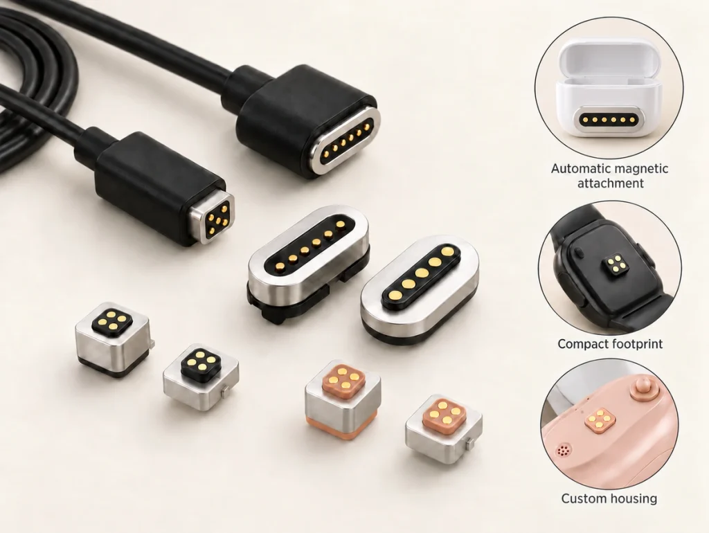
Square 4 Pin Magnetic Cable Connector
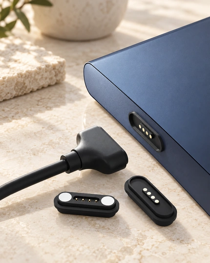
A square head can fit a specific enclosure opening and define the mating orientation. Its footprint and geometry guide the alignment of the male and female parts.
Send the opening dimensions, housing thickness, available mating area and intended outlet direction from the device drawing to review a square configuration.
Explore Related Hearing-Aid Applications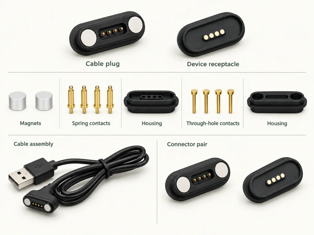
Custom 4 Pin Magnetic Charging Cable for Your Device
An existing PCBA position, housing thickness, charging port and exterior design may leave a standard cable with the wrong pitch, inadequate clearance or incorrect polarity.
Magtor can adapt dimensions, contact assignments, cable length, conductor specification, polarity, magnetic force and outlet direction to the confirmed device requirements.
What Is a 4 Pin Magnetic Charging Cable?
Magnets align the cable with the device-side connector. Four pogo pin contacts then create the electrical paths as the parts meet.
Four describes contact count, rather than a fixed USB pinout. Define power, ground and other signals according to the project circuit.
Explore all Magnetic Cable Connectors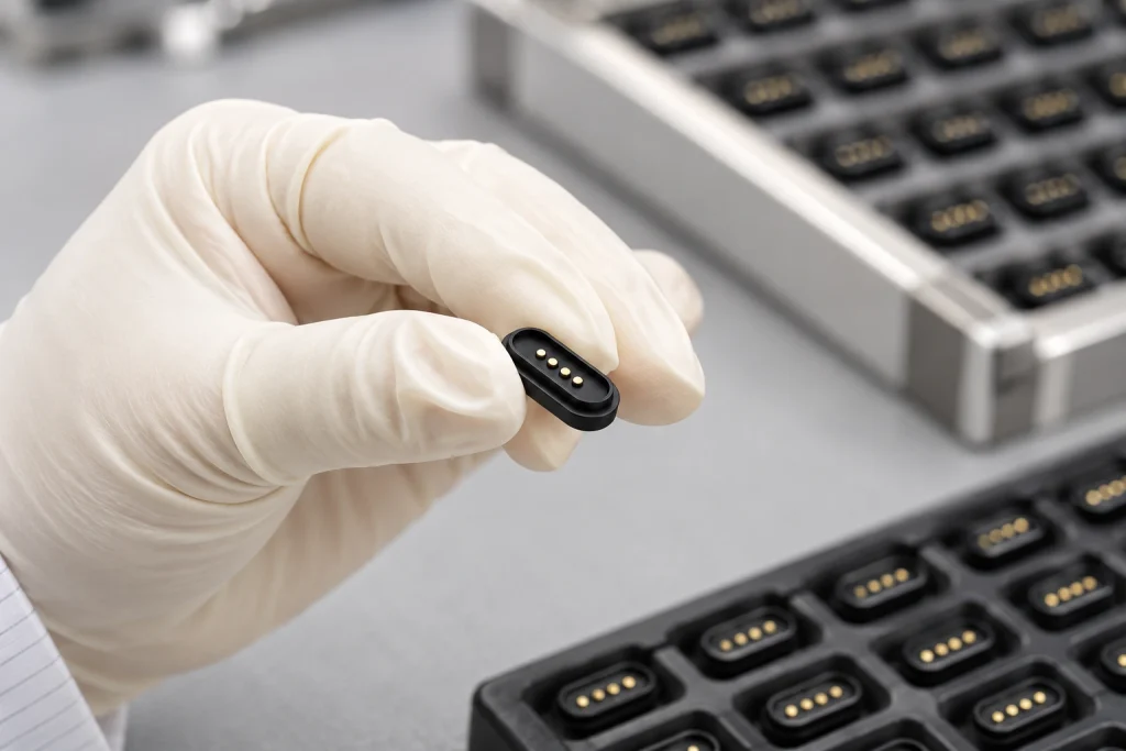
How Should the 4 Pins Be Assigned?
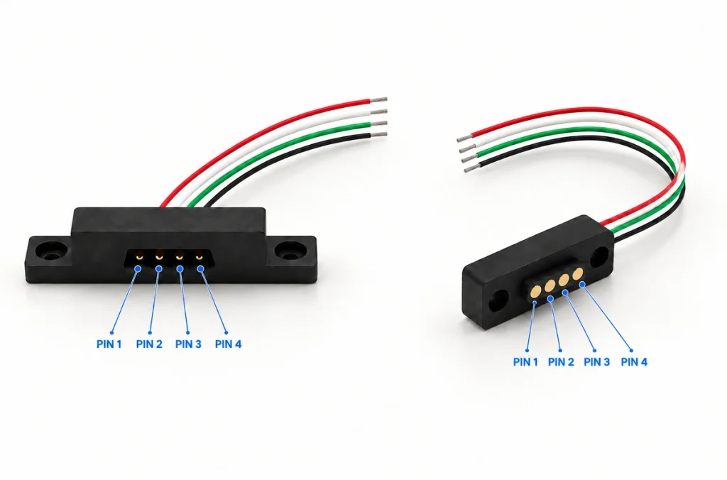
The approved contact map and device circuit determine whether the cable serves charging alone or power and signals together. The two examples below are design approaches, rather than assignments shared by every Magtor model.
Charging-Focused Layout
V+ (Power)
GND (Ground)
ID / Detection
Control / Reserved
Power + Signal Layout
Power
Ground
Signal 1
Signal 2
Interface Compatibility Checklist:
Choose the Cable End for Your Device
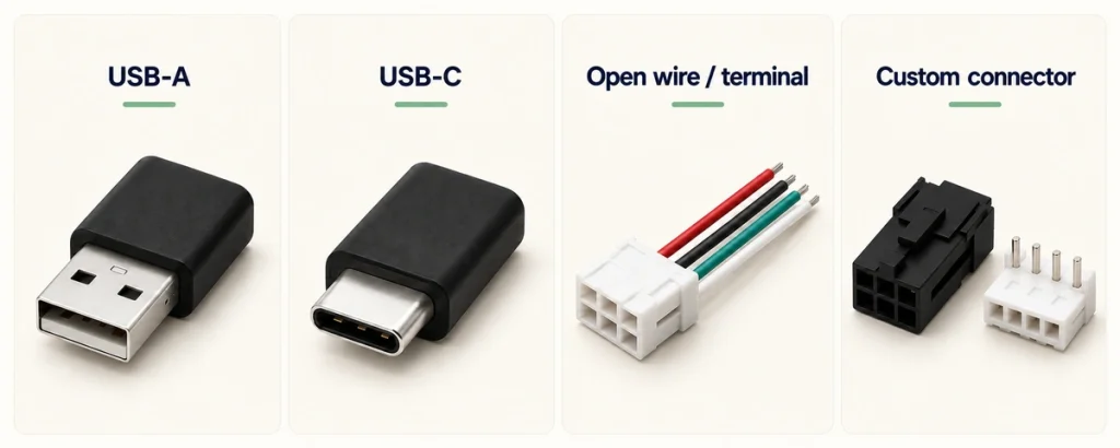
Choose a cable termination that matches the power source or internal harness.
USB-A
For common USB power supplies and charging accessories.
USB-C
A USB-C end can serve a modern power input. USB PD or fast charging also requires the appropriate circuit and wiring.
Open Wire / Terminal
For PCB leads, internal harnesses, docks and industrial integration.
Custom Connector
Use a specified connector to match an existing proprietary harness.
What Should You Confirm Before Ordering?
Supply these details so the cable assembly can be reviewed against the hardware design.
| Parameter | Why It Matters | What to Provide |
|---|---|---|
| Pin assignment | Define the power and signal routes. | Circuit diagram / definition |
| Voltage / Current | Select contact size and conductor gauge. | Confirm based on project specification |
| Pin pitch | Match the device-side contact positions. | Distance between pin centers |
| Electrical polarity | Check the electrical polarity to address short-circuit risks. | Positive/Negative layout |
| Cable outlet (90°/180°) | Review space around the cable outlet. | Housing constraints |
| Cable length & OD | Plan the cable path and permitted voltage drop. | Required dimensions (mm) |
Scroll horizontally to view every column.
Applications for 4 Pin Magnetic Charging Cables
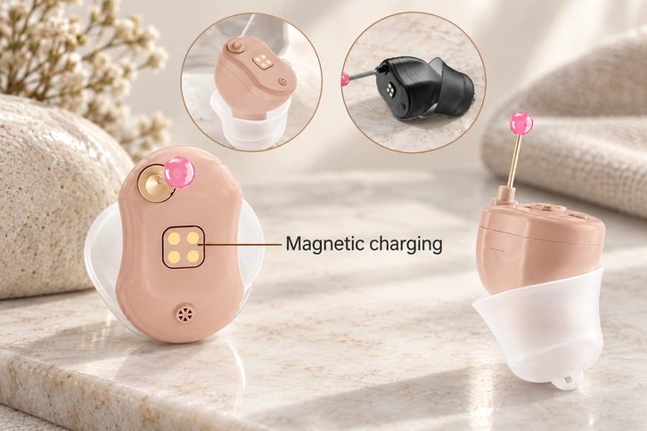
Smart Wearables
Magnetic guidance supports docking without visual alignment at a defined position. Square heads or open-wire ends are options for review.

Medical Electronics
Develop a connection for frequent use, practical external-cable replacement and cleaning of the interface.
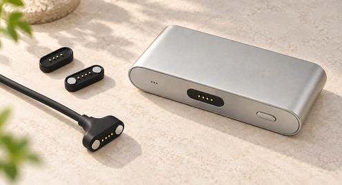
Consumer Applications
A rapid-release interface can support repeated connection. Tens-of-thousands cycle capability must be confirmed for the model; the listed card specification remains 10000+.
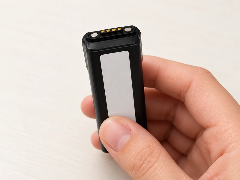
Handheld Devices
A handheld accessory may need frequent charging together with signals or ID detection.
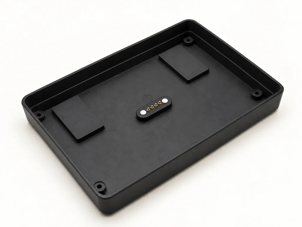
Control Panel
A control-panel interface can use rear sealing and connections to a data cable or dock where the engineering requirements call for them.
Industrial Electronics
Industrial panels may need power and signals together with a defined internal cable route.
4 Pin vs 2 Pin Magnetic Charging Cable
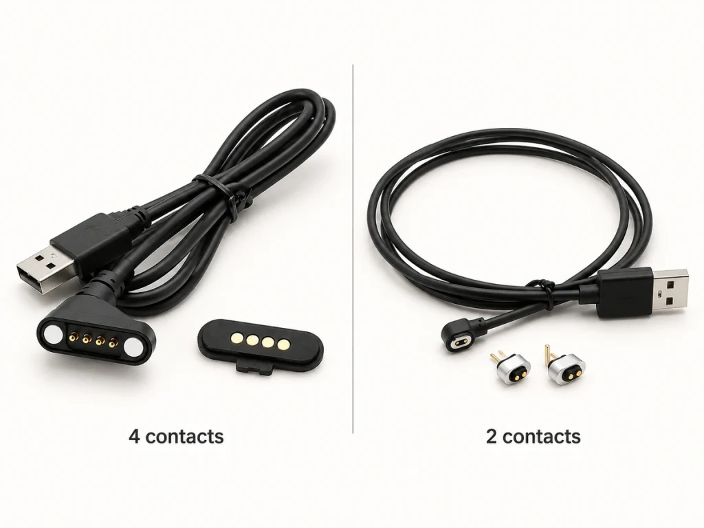
Select two or four contacts according to the device circuit and the electrical functions required.
2 Pin Magnetic Cable
Two contacts suit basic positive/negative charging in a small interface. View the 2-Pin Options for related configurations.
View 2 Pin Options4 Pin Magnetic Cable
Four contacts allow charging alongside additional signals, ID detection or status/control functions, depending on the chosen circuit.

How Are 4 Pin Magnetic Cables Checked?
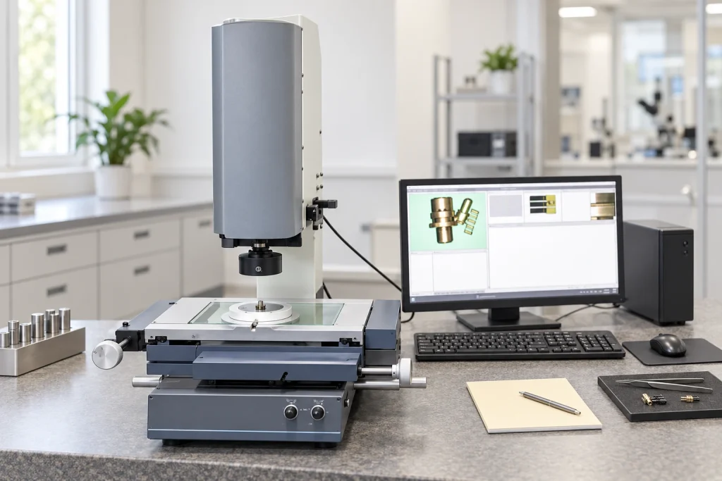
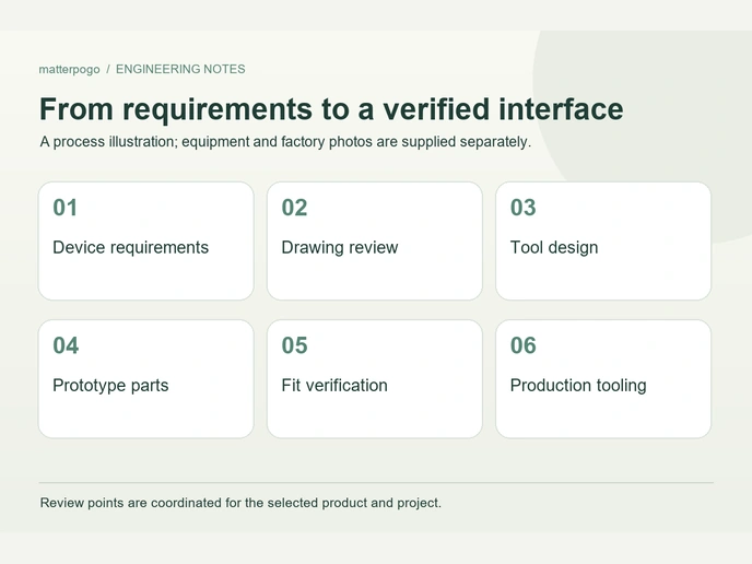
Magtor checks critical parameters to carry an approved sample design into production. Inspection covers conductor sequence, polarity, cable length and mating position for consistent assemblies.
Contact resistance
Spring force
Magnetic force
Cable continuity
Open / short test
Mating-cycle test
Dimensional measurement
Plating inspection
Why Develop a Custom Cable with Magtor?
Our 17 years of factory experience support precision design and connection development for OEM integration.

Custom Solution Development
Prototyping & Mold Making
17 Years of Connector Manufacturing
From design to mass production,

Dedicated Connector Factory
A workforce of 185 includes 12 R&D staff at our 12000-square-meter factory. This professional team supports customers with technical and manufacturing services.

Production Equipment and Technical Expertise
Our technical team works with advanced production equipment to maintain consistent connector output and performance.
Inspection and Testing
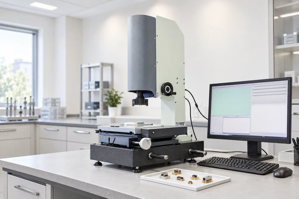
Connector checks include lifespan, film thickness, elastic resistance, RoHS compliance and CCD inspection, using advanced test equipment.
Engineering Support Customers Can Rely On
More than a dozen technical engineers review connector proposals carefully against the requirements of each application.

Automated Production
17 years of manufacturing experience support concept development through mass production, with technical guidance and prompt project responses.
Supporting More Than 500 Enterprises Worldwide










1 / 10
Management Systems and Certificate Documents
ISO 9001
ISO 14001
QC080000
Frequently Asked Questions
What are the four pins used for on a magnetic charging cable?
Does every 4 pin magnetic charging cable support data?
How do I know if a 4 pin magnetic charger is compatible with my device?
Should I choose a 90° or 180° magnetic cable?
Can the cable length and wire gauge be customized?
Can a 4 pin magnetic cable use USB-C?
Can Magtor match a cable from a sample or drawing?
What information is required before developing a custom 4 pin cable?
Request a Custom Solution Quote
Share your project with our engineering team. Our 17 years of manufacturing experience support precision design and prototyping around the needs of your company.
Email Us
Contact details to be suppliedCall / WhatsApp
Contact details to be suppliedHeadquarters
406, Building 3, No. 12, Zhenyuan Road, Wusha, Chang'an Town, Dongguan City, Guangdong Province, China