6-Pin Magnetic Cable Assemblies for Your Device
A detachable six-contact magnetic interface can combine power, charging and signal paths in one cable assembly. Choose USB, bare-wire or terminal ends around the integration needs of your device.
- Home
- Magnetic Cable Connector
- 6 Pin Magnetic Charging Cable
6 Pin Magnetic Charging Cable Options
Choose the cable construction for external charging, internal wiring or prototype evaluation.
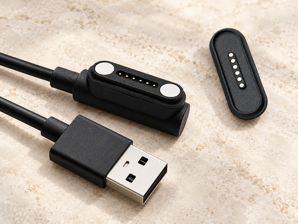
6 Pin Magnetic Cable Connector
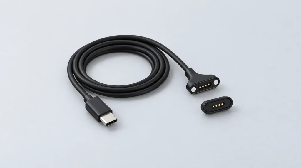
A full assembly with a standard USB end can connect to an external adapter or suitable host. Its matching device connector is integrated into the housing; data functionality requires the appropriate wiring and circuit.
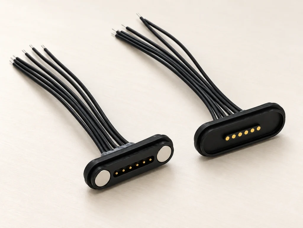
6 Pin Magnetic Connector Cable Bare Wire
Open leads allow the engineer to specify strip lengths and conductor colors for direct PCB soldering or prototype evaluation.
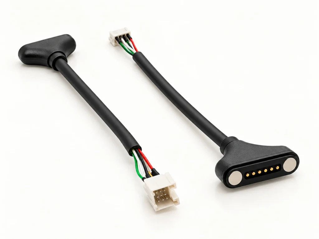
Custom 6 Pin Magnetic Connector Cable
A project-selected terminal turns the cable into an internal harness. Match the terminal to the mating connector and PCB interface for repeatable production assembly.
Design the Cable and Device Connector Together
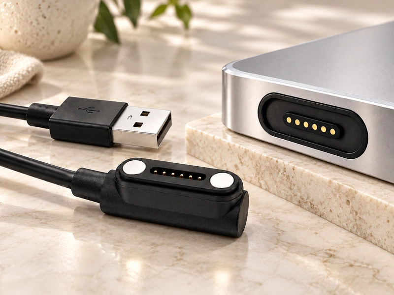
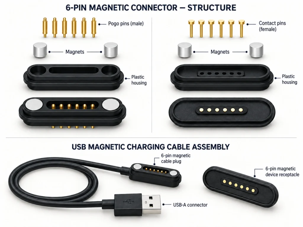
Design both mating sides together. The cable assembly needs a compatible device-side interface to form a complete system.
magnetic charging cable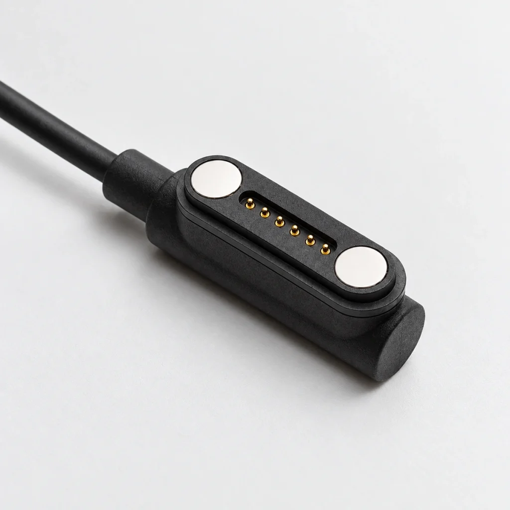
Cable-Side Head
Cable-side magnetic head for the power or signal input.
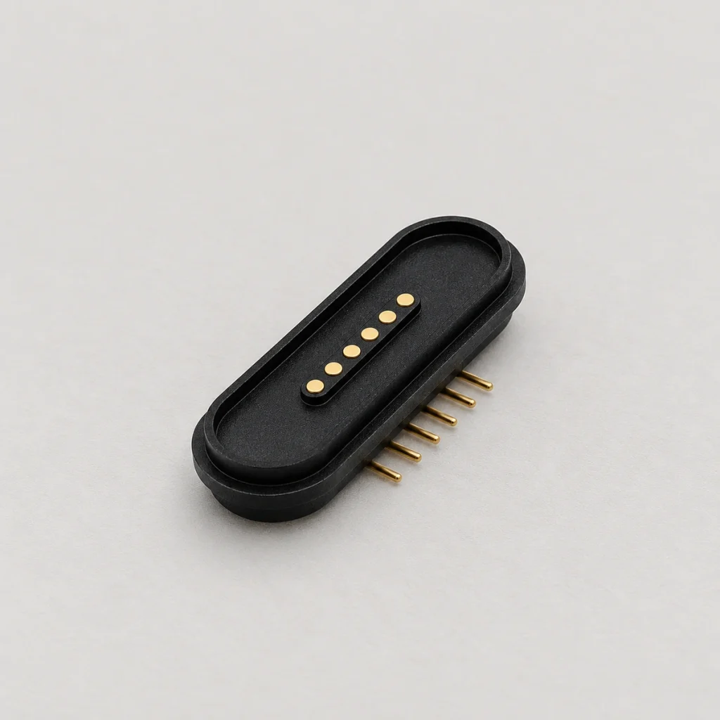
Device-Side Connector
Device-Side ConnectorMatching six-contact magnetic interface mounted on the device PCB.
6 pin magnetic connectorConfirm direction, magnetic polarity, housing opening, connector height, PCB position, contact compression and pull direction together before selecting the assembly.
6 Pin Magnetic Cable Specifications
Each OEM application defines its own electrical and mechanical requirements. Specifications depend on the chosen cable structure and the device integration.
Reference Configuration Example
The example below describes one catalog configuration. Different pitches, current requirements and cable constructions can be reviewed for a custom device.
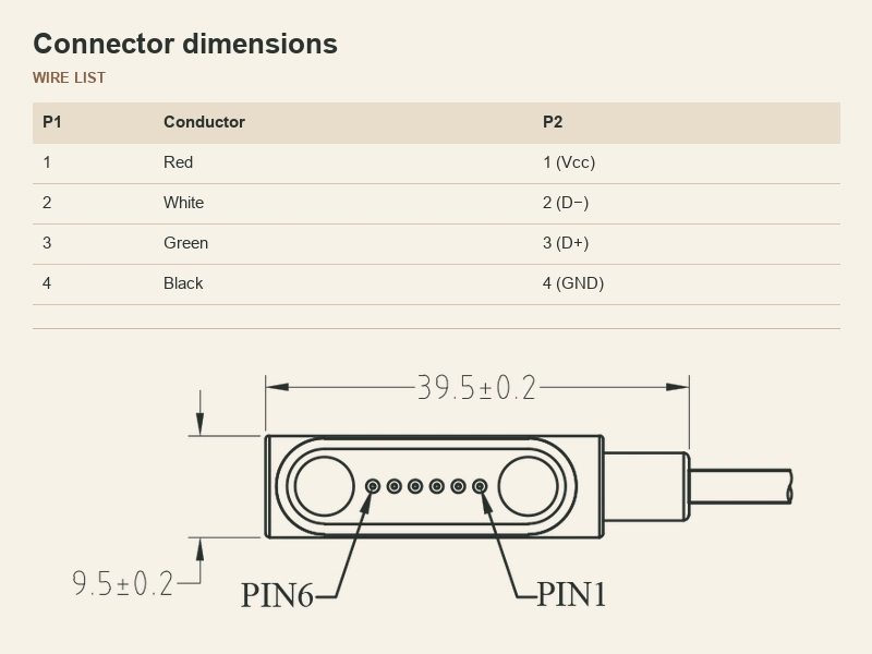
Type: 6PIN M/F
Pitch: 2.0 mm
Current: 3A
| Parameter | Value / Range |
|---|---|
| Pin Count | 6 Contacts |
| Pin Pitch | 2.0 mm |
| Rated Current | Configurable by project |
| Rated Voltage | Defined according to device requirements |
| Magnetic Force | Available according to the selected structure |
| Cable Length & Gauge | Customizable |
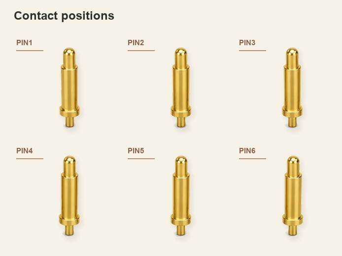
| Pin Assignment | Defined from the device schematic |
Scroll horizontally to view every column.
What Is a 6 Pin Magnetic Charging Cable?
A six-contact charging cable is a detachable assembly with a magnetic mating head and six electrical paths.
Engineers can assign those paths to power, ground, data, identification or control. The interface supports OEM integration between an external source and the internal PCB, with performance validated for the approved design.
What Can 6 Pins Be Used For?
Six contacts offer more circuit-allocation options than two or four contacts. They do not define a universal six-contact magnetic pinout.
Contact count describes the physical interface, rather than a protocol. Depending on the device electronics, the contacts can serve:
Use the device schematic, voltage and current, and signal requirements to define each contact.
Can a 6 Pin Magnetic Charging Cable Carry Power and Data?
A six-contact cable can carry power and signals together if its contact map, conductors and device electronics are designed for those functions.
Six contacts alone do not establish USB or data capability. Review current on each power path, ground return, signal allocation, conductor size, signal integrity and contact resistance before approving a power/data cable.
Choose the Cable End for Your Device
Specify the cable end for the external source or the internal production-assembly process.
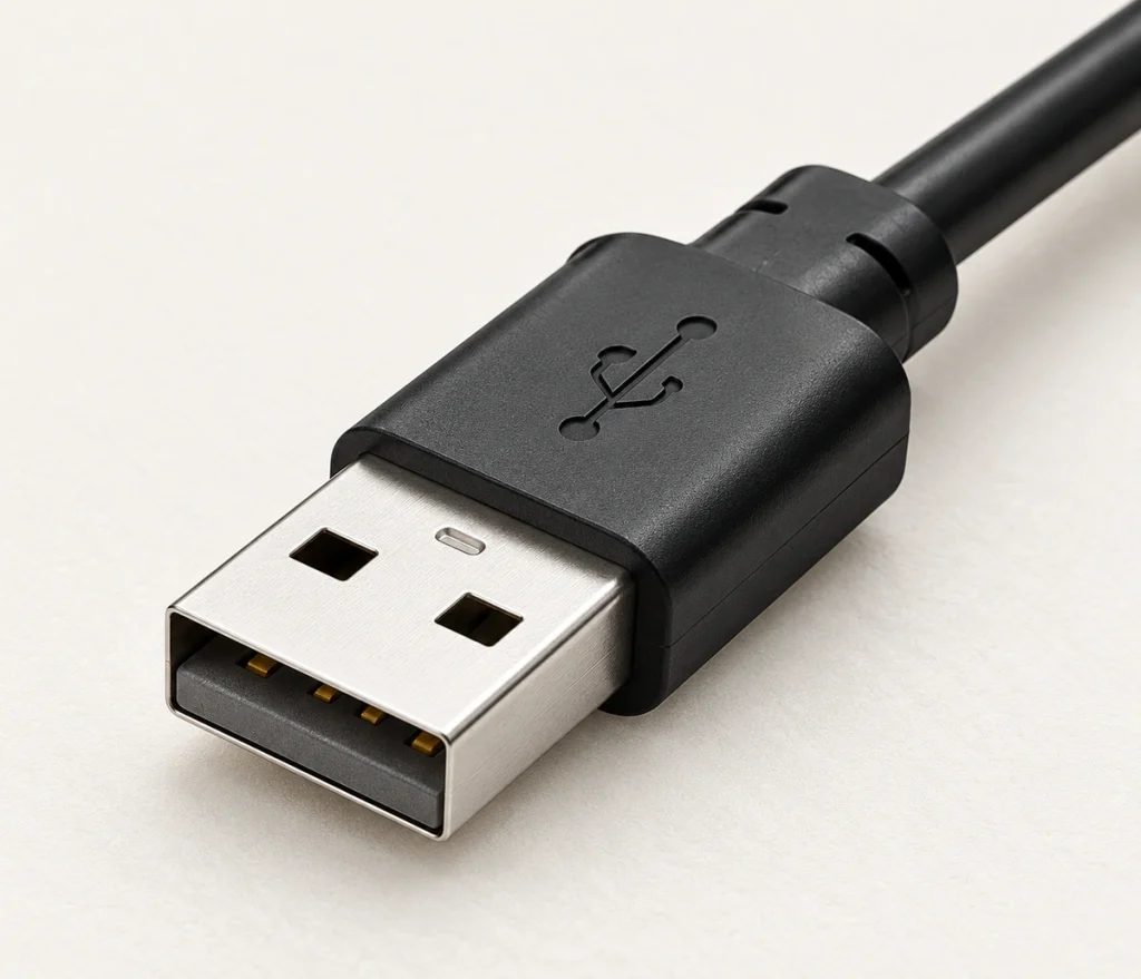
USB-A
For external charging adapters or suitable standard host interfaces.
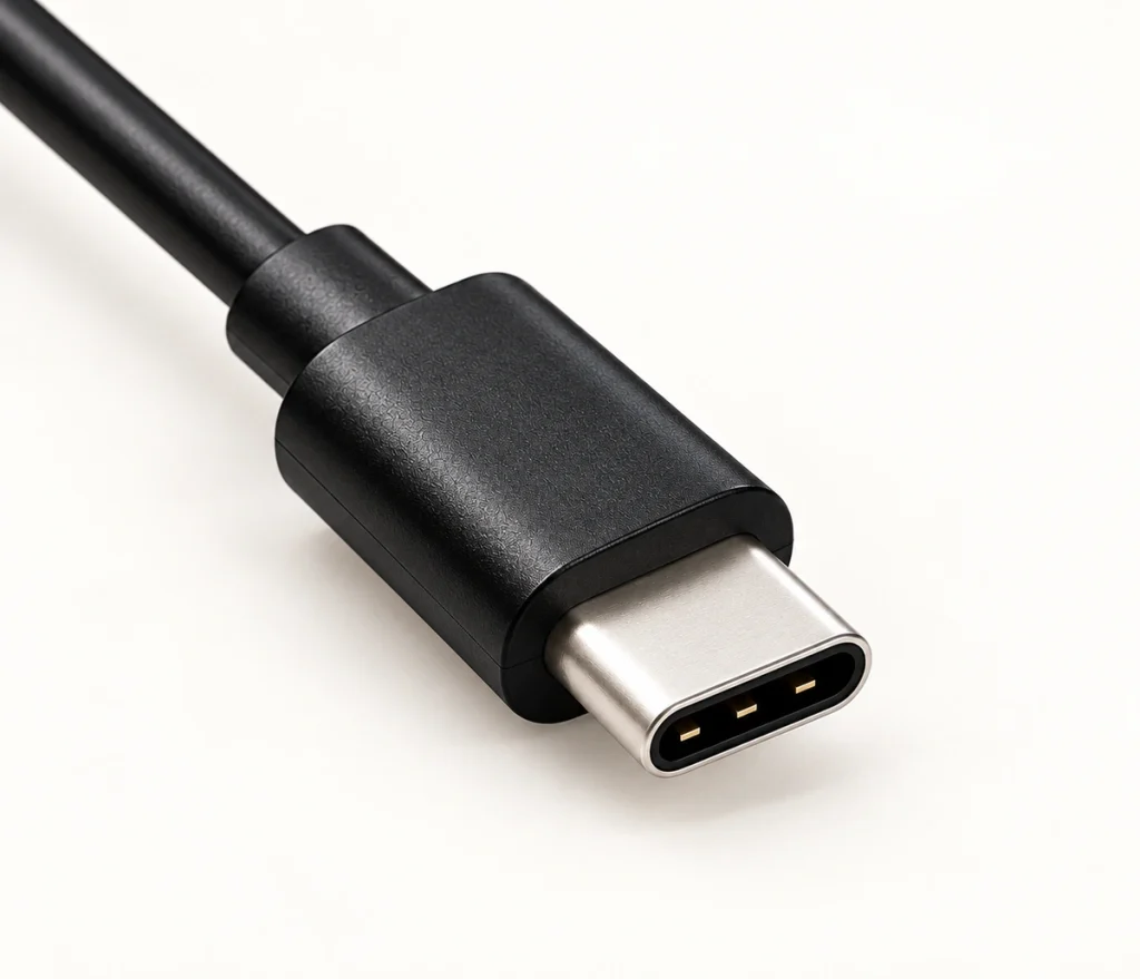
USB-C
A USB-C end can connect to modern power sources and compact host ports. Its shape alone does not establish PD or data capability.
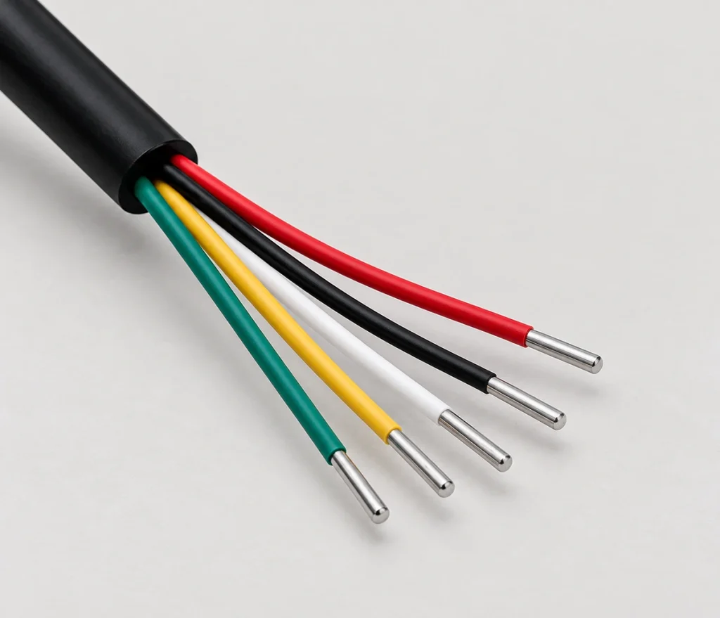
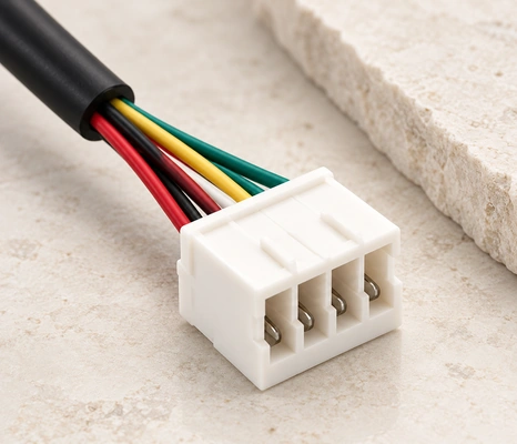
Terminal Connector
Terminal ConnectorA terminal end creates an internal PCB harness and simplifies repeatable assembly.
Configure the Cable Around Your Device
Match the head to the enclosure, PCB position and cable route rather than choosing only by contact count. When the PCB and housing are fixed, adapting the cable can reduce connector redesign before prototype approval.
Connector housing & pitch
Magnetic polarity & force
Cable length & wire gauge
Strain relief design
90° or 180° cable outlet
Waterproof structure (if applicable)

Where Are 6 Pin Magnetic Charging Cables Used?
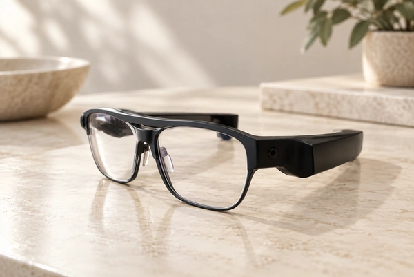
Wearable Electronics
A smartwatch or fitness tracker can use several contacts for charging, ground and data within a small housing opening.
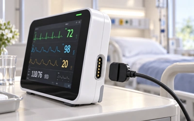
Medical Devices
Patient monitors and diagnostic tools may assign additional contacts to detection, ID or sensor signals alongside power. Medical requirements need complete-device validation.
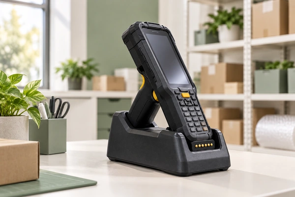
Industrial Handhelds
Industrial scanners and field terminals can combine rapid magnetic docking with charging and communication functions suited to their circuits.
Smart Hardware
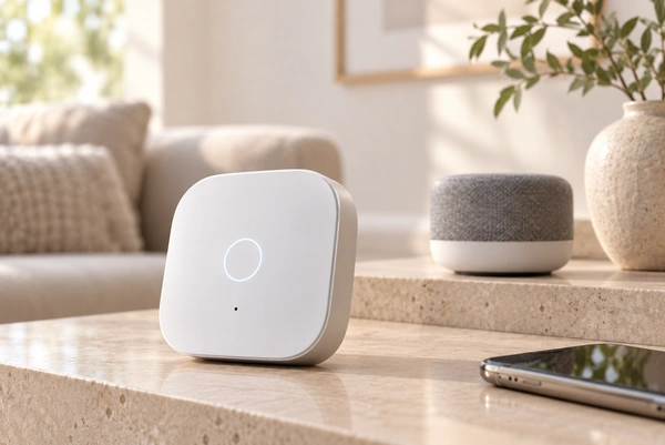
IoT and smart home hardware can allocate separate contacts to power and control.

Robotics
AGVs and service robots can use additional power and ground paths to meet charging requirements, with current distribution validated for the design.

Weed-Removal Robot
A weed-removal robot can use quick magnetic attachment with corrosion and vibration protection specified for its operating environment.

Testing for Repeated Charging and Mating
For repeated-docking projects, laboratory equipment can be used to evaluate sample contact stability before production.
Cycle-Life Testing
Evaluate repeated mating for docks and portable devices that connect frequently.
DC Low-Resistance Testing
Identify unstable contact paths before approving the cable design.
Salt-Spray & Temperature Testing
Specify salt spray evaluation for humid or corrosive exposure. Temperature-rise equipment can assess thermal performance under the required load.
From Device Drawing to Cable Production
Sample timing depends on whether an existing interface is suitable or a new housing, tool or termination needs development.
Requirement Review
Agree on the contact map, device drawing and electrical requirements.
Prototype / Sample
Make samples for mechanical and electrical evaluation.
Sample Approval
The customer confirms cable routing and repeatable mating.
Mass Production
A pilot run precedes volume manufacture with the required checks.
Professional Manufacturer of 6-Pin Magnetic Data Cables
More than a decade of spring-contact and magnetic connector development supports our in-house production and R&D teams. Advanced test equipment and repeated production checks are used to assess connector quality.
2009 — confirmation pending
Founded
12,000 m²
Factory Area
185
Employees
ISO 9001 / ISO 14001 / QC 080000
Project relationships include hardware teams at Intel, Medtronic, a device manufacturer, Lenovo, Hisense, SANY, Sunwoda and TCL.

17 Years of Connector Manufacturing
From design to mass production,

Dedicated Connector Factory
A workforce of 185 includes 12 R&D staff at our 12000-square-meter factory. This professional team supports customers with technical and manufacturing services.

Production Equipment and Technical Expertise
Our technical team works with advanced production equipment to maintain consistent connector output and performance.
Inspection and Testing
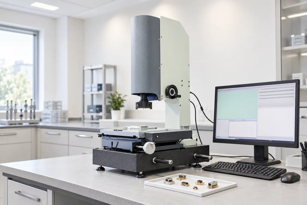
Connector checks include lifespan, film thickness, elastic resistance, RoHS compliance and CCD inspection, using advanced test equipment.
Engineering Support Customers Can Rely On
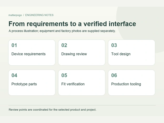
More than a dozen technical engineers review connector proposals carefully against the requirements of each application.

Automated Production
17 years of manufacturing experience support concept development through mass production, with technical guidance and prompt project responses.
Supporting More Than 500 Enterprises Worldwide










1 / 10
Management Systems and Certificate Documents

ISO 9001
ISO 14001
QC080000
Related Magnetic Cable Solutions
Magnetic Cable Connector
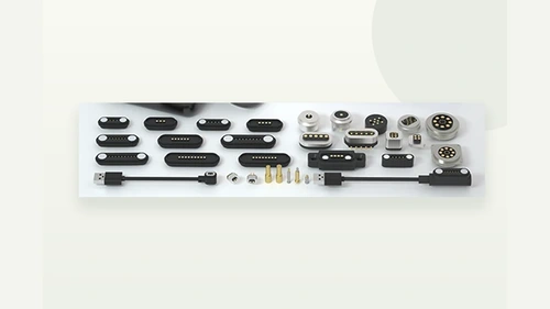
1–16-contact cable options with USB-A/USB-C ends and 90°/180° routing.
Magnetic Cable Connector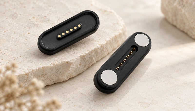
6 Pin Magnetic Connector
Review the matching device-side six-contact interface.
6 Pin Magnetic Connector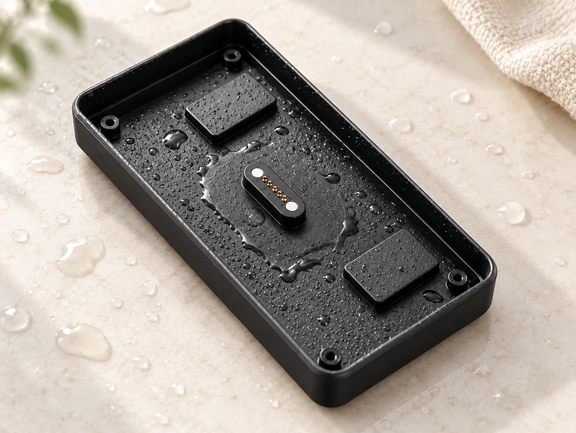
Waterproof Magnetic Connector
Project-specific waterproof interfaces targeting IP65–IP68.
Waterproof Magnetic ConnectorFrequently Asked Questions
Is there a standard pinout for a 6 pin magnetic charging cable?
Can I use different pins for charging and data?
Can the cable be supplied with bare wires instead of USB?
Can you add a terminal connector at the cable end?
Do I need the device-side magnetic connector as well?
Send Us Your 6 Pin Cable Requirements
Provide the following details to support an efficient engineering review of your cable project:
Device drawing or housing opening
Required pin functions (power, data, etc.)
Voltage and current requirements
Cable length and wire gauge (if specified)
Cable end (USB, bare wire, terminal)
Annual quantity and target environment