
laptop magnetic contact charging and Pogo Pins: What the Evidence Shows
Published on August 18, 2026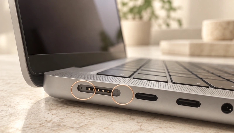
- laptop magnetic contact charging charging architecture
- What the spring-contact evidence establishes
- How guidance and contact pressure work together
- laptop and smartphone magnetic wireless charging compared
- Design roles of spring contacts
- Developing a dedicated magnetic charging interface
laptop magnetic contact charging transfers charging power through conductive contacts, with magnets assisting attachment and retention. the reference manufacturer’s earlier magnetic-connector patent describes spring-loaded pins meeting flat contacts, a mechanism similar to pogo-pin interfaces. That historical description does not establish the internal construction of every current magnetic charging 3 product.
For a custom charger, useful engineering concepts include guided mating, compliant electrical contacts, controlled removal and power management. Those concepts can be evaluated for wearables, medical equipment, smart products, charging docks and industrial devices without implying the reference manufacturer compatibility or supply relationships.
dedicated magnetic spring-contact chargerslaptop magnetic contact charging charging architecture
magnetic charging is the reference manufacturer’s dedicated magnetic charging interface. Supported laptop models can use a USB-C to magnetic charging 3 cable with a compatible USB-C adapter; USB-C charging is also available on supported models. Consult the reference manufacturer’s guide for the exact equipment. magnetic charging 3 cables and adapters are not interchangeable with earlier magnetic charging generations.
The reference manufacturer’s Mac charging and compatibility guide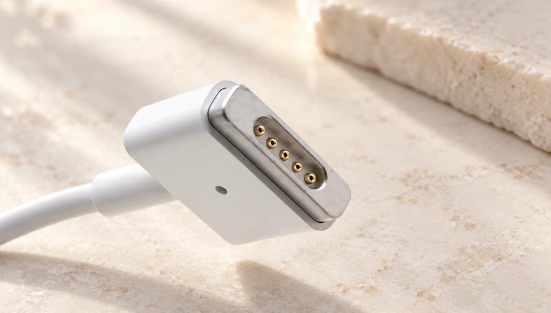
Where USB-C uses a plug inserted into a receptacle, laptop magnetic contact charging attaches magnetically against its matching port. Guidance and retention come from the designed magnetic arrangement.
A simplified power path is:
Power adapter → magnetic charging cable → Magnetic mating assembly → Conductive contacts → laptop charging electronics → Battery
Magnets mainly guide and retain the joint in this architecture. Metal contacts carry power across the mating interface.
That makes laptop magnetic contact charging contact-based magnetic charging rather than inductive wireless charging.
For a broader interface choice, see Magtor’s comparison of dedicated magnetic contacts and USB-C.
Magtormagnetic contacts and USB-C comparedWhat the spring-contact evidence establishes
The reference manufacturer’s earlier connector patent supports a spring-loaded contact mechanism closely related to pogo-pin operation. Current consumer instructions describe magnetic charging 3 use and compatibility, but do not establish every model’s internal spring-contact structure.
In the patent’s preferred embodiment, plated pins are urged outward by springs to engage corresponding flat contacts. Magnetic elements hold the mating sides in the conductive position. This is historical design evidence, not a verified cross-section of every current connector.
earlier magnetic-connector patent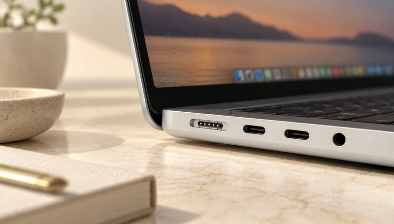
Reports of earlier magnetic charging teardowns use the term “pogo pins.” Without a specific linked model and teardown record, that description should not be used to verify the construction of current magnetic charging 3 hardware.
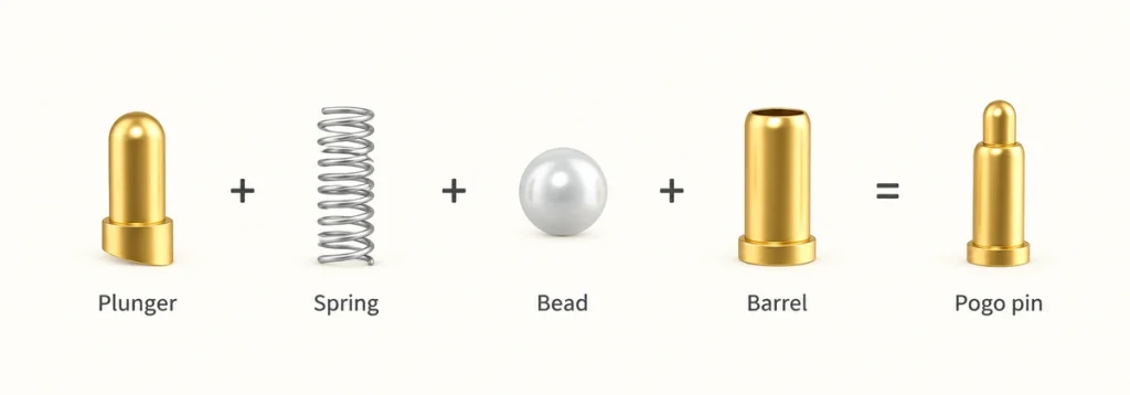
A typical spring contact has three main parts:
Plunger
Spring
Barrel
During mating, the plunger moves into the barrel and compresses the spring. Contact pressure depends on keeping the pin within its specified working travel.
Commercial spring contacts use the same general compliance principle to accommodate specified mechanical variation. Their suitability for repeated mating, shock or vibration depends on the actual product and test conditions; those capabilities cannot be inferred for a custom assembly from another manufacturer’s description.
commercial spring-loaded contactsKeep the product distinction clear:
The reference manufacturer’s magnetic charging is a dedicated interface, not a generic off-the-shelf pogo-pin part. Similar contact mechanics do not establish matching dimensions, wiring or control functions.
The reference manufacturer’s consumer materials call the current interface magnetic charging 3. The historical contact description and the current compatibility guide answer different questions.
Design note: The earlier the reference manufacturer patent describes magnetic retention with spring-loaded conductive contacts. It supports the mechanism comparison, not a claim that a generic magnetic pogo-pin assembly is compatible with the reference manufacturer equipment.
How guidance and contact pressure work together
A magnetic contact system separates mechanical positioning and retention from electrical conduction.
Magnets supply the attachment force; engaged spring contacts supply the conductive paths in the mechanism described here.
The general engagement sequence can be explained in five stages:
1. The mating halves approach
Within the magnetic capture range, attraction can begin before full electrical engagement. Actual distance and sequencing depend on the design.
2. Magnetic guidance assists placement
Attraction helps bring the charging head to its intended position, with the mating geometry controlling final alignment.
3. The conductive surfaces meet
In a spring-contact design, the pins compress against their corresponding pads or plates as the surfaces engage.
4. Compression provides contact pressure
Permitted spring travel can accommodate limited manufacturing and mating-height variation. It does not compensate for arbitrary lateral misalignment.
5. Retention maintains engagement
The magnetic joint holds the assembly while the engaged contacts carry power within the designed electrical limits.
The earlier patent describes this relationship between spring-loaded pins, flat receptacle contacts and magnetic retention. It should be read within that embodiment’s scope rather than as a model-by-model verification of today’s hardware.
A dedicated magnetic pogo-pin charger can use the same general division of functions:
magnetic spring-contact charging interfaceMagnets → guidance and retention
Spring contacts → conductive electrical connection
The device requirements shape retention, contact travel, contact layout, housing form and cable exit. Review these together, including the spring reaction and mechanical stop conditions.
A simple supply interface may need a positive path and return. More contacts can provide data, detection, identification or control functions where the pinout and circuitry support them.
laptop and smartphone magnetic wireless charging compared
Both use magnetic positioning, but charging power crosses the interface differently: laptop charging uses conductive contacts, while the smartphone magnetic wireless charging uses induction.
| Architecture factor | laptop magnetic contact charging | smartphone magnetic wireless charging |
|---|---|---|
| Charging method | Power through metal contacts | Inductive wireless power transfer |
| Magnetic alignment | Yes | Yes |
| Physical electrical contacts | Yes | No conductive charging-power connection across the phone surface |
| Spring-contact mechanism | Described in the earlier connector patent; current model details are not established here | Not the inductive power-transfer mechanism |
| Power transfer | Conductive contacts | Electromagnetic induction |
| Cable-to-device physical contact | The cable connector meets the computer’s contacts | The charging surface can physically touch the phone while power transfers inductively |
| Main purpose of magnets | Connector positioning and retention | Charging-coil alignment and accessory attachment |
Scroll horizontally to view every column.
The reference manufacturer’s smartphone magnetic wireless charging guide describes wireless charging with the phone positioned on its magnetic charging surface. Check the guide for supported equipment and adapter conditions.
The reference manufacturer’s smartphone magnetic wireless charging guideFor laptop contact charging, current instead crosses through the conductive mating contacts.
As a conceptual comparison:
laptop magnetic contact charging
Magnets → connector positioning; metal contacts → electrical power transfer
smartphone magnetic wireless charging
Magnets → coil alignment; electromagnetic induction → power transfer
Magnetic attachment can be used in both architectures, while the underlying power-transfer methods differ.
Architecture affects mechanical packaging, sealing, thermal behaviour, efficiency, PCB space and product thickness. Compare these for the complete device rather than assuming a measured advantage from the mechanism alone.
A conductive magnetic pair may suit a small envelope, direct power paths, additional signals or a dedicated charging layout, subject to the required validation.
Induction may suit a design whose priority is power transfer without exposed mating power contacts. It still requires compatible coils and control electronics, and does not automatically establish waterproofing.
Design roles of spring contacts
Spring compliance can accommodate limited axial variation while maintaining engagement in the specified working range. Magnetic retention and housing alignment must support that condition.
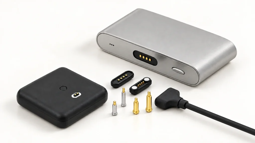
Repeated docking, varying mating heights, tolerances, shock and vibration are inputs when selecting spring contacts. Verify the chosen assembly against those requirements rather than transferring a supplier’s general description into a product rating.
spring-contact design informationSix design roles to consider are:
Guided attachment
Magnets can assist placement without conventional plug insertion. The housing and polarity still define the correct mating position.
Contact pressure within the working range
A compressed spring keeps the plunger against its mating surface when working height and retention are suitable.
Accommodation of axial variation
Specified contact travel can absorb limited differences in enclosure position, PCB height, assembly tolerance and mating distance.
Controlled removal
A magnetic joint can release without deep plug insertion. Validate the required separating force, direction and support of the device.
A shallow device-side contact area
Matching pads can provide a relatively flat contact surface where the product’s mechanical and sealing design allows it.
Product-specific contact allocation
The available paths can serve:
Power
Ground
Data
Connection detection
Device-identification signals
Charging control
Five- and six-contact assemblies offer additional allocation choices for power and signals. Choose the functions from the application; neither contact count nor appearance establishes protocol support.
five-contact magnetic assemblysix-contact magnetic assemblyPossible applications include wearables, medical electronics, smart-home products, handheld equipment, robots, charging cradles and industrial devices requiring a dedicated interface. Assess safety and compatibility for the specific product.
Review allowable current, voltage drop, resistance, temperature rise, contamination, corrosion, mating life, short-circuit protection and retention before selection. Spring contacts and magnets alone do not make an assembly suitable for every project.
Developing a dedicated magnetic charging interface
A product can be designed for guided attachment and controlled removal without claiming compatibility with the reference manufacturer’s magnetic charging interface. The comparison concerns a handling concept, not authorization or a legal clearance conclusion.
The general architecture combines:
Magnets + spring-loaded contacts + matching pads + power/signal electronics
Develop the interface against the particular product’s electrical and mechanical requirements.
Begin with these six development inputs:
1. Set supply and thermal requirements
Specify maximum operating voltage, charging current, permitted voltage drop and thermal limits before choosing the contact structure.
Higher loads may call for larger contacts, lower resistance, larger conductors or parallel paths. Assess current sharing and installed temperature rise; parallel contacts do not automatically multiply a single-pin rating.
2. Determine the required contact count
A simple power-only example may use two paths:
V+ + GND
An interface with more functions may require:
V+ + GND + Data + ID + Detection + Control
Multiple contacts can accommodate a mix of supply and signals where the corresponding circuitry and return paths are defined.
3. Approve the electrical allocation
Allocate contacts from load current, electrical safety, PCB layout, engagement sequence and protection strategy. Define the mating views and numbering on both halves.
Exposed contacts may require reverse-polarity protection, short-circuit control, current limiting or controlled energization. Verify the actual mating and fault states.
4. Define working height and travel
Keep the engaged spring contact within the manufacturer’s recommended compression range at the permitted assembly tolerances.
Insufficient compression can produce unreliable contact.
Excessive compression can increase stress and wear.
5. Define retention and release targets
Retention must support electrical engagement and spring reaction without making intended removal difficult or overloading the enclosure. Evaluate the housing and stops with the magnetic system.
The target depends on connector size, device weight, cable exit, intended release action, vibration and handling requirements.
6. Fit the housing and cable exit
A dedicated magnetic assembly can be developed for the available product envelope. Custom geometry does not establish interoperability with standardized USB or proprietary equipment.
Mechanical inputs include:
Available connector length and width
Pin pitch
Contact locations
Board mounting arrangement
Magnetic polarity
Housing material
Cable exit direction
90° or 180° cable exit orientation
Required sealing structure
A dedicated magnetic spring-contact pair can offer guided attachment resembling the handling concept associated with magnetic charging. It should remain a separately designed interface, without an the reference manufacturer compatibility or authorization claim.
Magtor can discuss a magnetic contact assembly for charging, power, signals and docking. Review contact count and assignments, working height, retention, dimensions, finish, housing and cable together for the product and its validation requirements.
Related guides explain magnetic pogo-pin charging and compare dedicated magnetic interfaces with USB-C. Use them to review mechanism and interface priorities alongside the device requirements.
magnetic spring-contact charging guidededicated magnetic interfaces and USB-C comparisonThe comparison highlights a useful separation of functions: magnets guide and retain, while compliant conductive contacts can carry power. For another product, develop and validate the supply, signals, geometry, environment and handling independently; a similar attachment action does not establish magnetic charging compatibility.
Related reading