
Magnetic Connectors and USB-C: Compare the Complete Interface
Published on August 4, 2026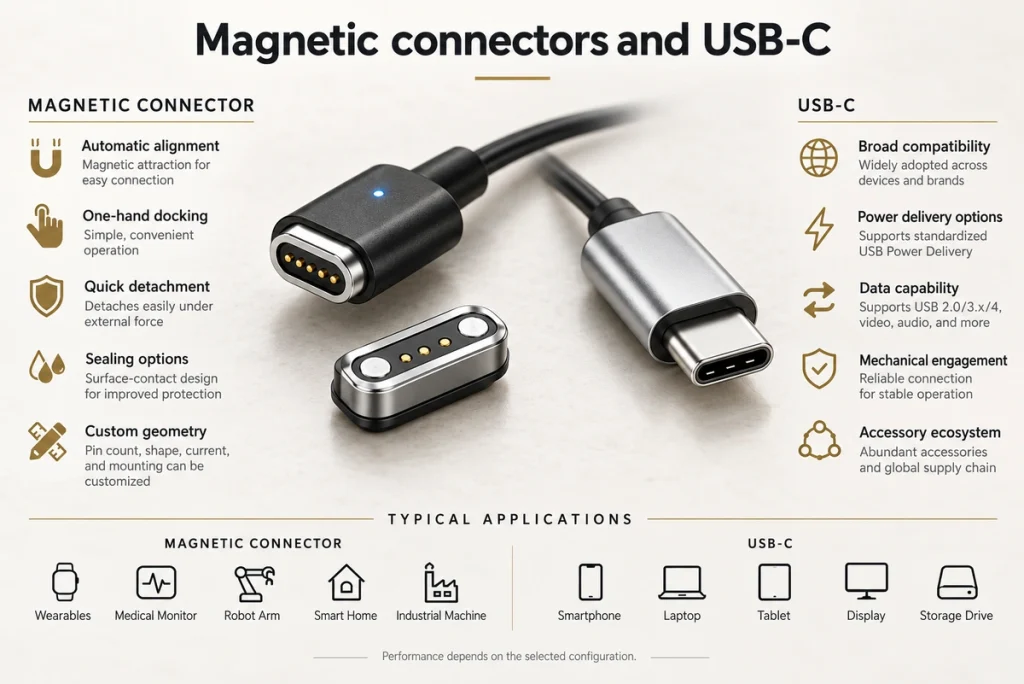
- Understanding Magnetic Mating
- Understanding USB-C
- Twenty Comparison Factors
- How the Interfaces Make Contact
- Four Practical Trade-offs
- Selecting Against Project Requirements
- Interface Selection Questions
Magnetic mating can simplify attachment and controlled release. USB-C® offers a standardized interface and a broad ecosystem, with power, data and video features determined by the actual devices and cable. Choose against electrical needs, mechanical integration and handling, rather than expecting either format to meet every requirement.
Understanding Magnetic Mating
Magnetic electrical interfaces use attraction to assist attachment and release. Charging and data-related designs can benefit where convenient handling and lower insertion wear matter, provided the contact system, release behavior and electrical protection meet the use conditions.
Magnetic connectorsContact system: Magnets guide and retain the pair; conductive pins or pads carry the electrical paths. The contacts are not necessarily magnetized.
Construction: The housing may use aluminum, stainless steel or other suitable materials, while magnets, conductive contacts and insulation perform separate roles inside the head.
Compatibility: Many magnetic interfaces are product-specific. Check the mating geometry, assignment and electrical specification before pairing parts.
Video material pending replacement
Understanding USB-C
USB-C defines a standardized connector interface used across computers, phones, tablets and other electronics. A supported implementation can provide high-speed data, charging, video or storage connections, but the connector shape alone does not establish those capabilities.
USB-CPhysical layout: The full-featured USB-C contact arrangement has 24 positions and supports reversible mating. Reduced-feature implementations and cable wiring do not necessarily implement every contact or function.
24-position contact layoutConstruction: Connector durability depends on the selected part, its mounting and its specified operating conditions.
Compatibility: The ecosystem supports many device categories, but each connection needs compatible devices, cable and implemented protocols.
Video material pending replacement
Twenty Comparison Factors
| Comparison Factor | Magnetic Connector | USB-C |
|---|---|---|
| Connection Method | Uses magnetic attraction for automatic alignment and connection | Requires a plug to be manually inserted into a receptacle |
| Standardization | Usually customized without a universal interface standard | Highly standardized with established specifications |
| Compatibility | Generally designed for a specific device or product series | Broad ecosystem; verify device, cable and protocol compatibility |
| Data Transmission | Best suited for charging, control signals, and low- to medium-speed data | Can support high-speed data, video and audio with the required implementation |
| Power Capability | Can be customized by changing contact size, quantity, and layout | USB Power Delivery available when implemented |
| Ease of Use | Magnetic guidance with suitable geometry and polarity | Reversible, but still requires manual alignment and insertion |
| Accidental Cable Pulling | Designed release can reduce pull damage; verify direction and force | Usually remains connected and may transfer pulling force to the device |
| Connection Stability | Magnetic holding force must be carefully designed for vibration environments | Mechanical engagement can provide secure retention; verify the model |
| Mating Durability | Depends on pogo pin structure, plating, spring force, and contact cleanliness | Check the selected part’s defined mating-cycle specification |
| Waterproof Design | Surface-contact layouts can simplify enclosure sealing | Receptacle sealing needs an appropriate complete enclosure design |
| Dust Resistance | Surface contacts are easy to clean but magnets may attract metal particles | Dust, fibers, and debris may accumulate inside the receptacle |
| Connector Size | Can be customized for compact, thin, circular, oval, or irregular products | Dimensions and mating structure are restricted by USB-C specifications |
| Customization | Pin count, shape, magnetic force, current, cable, and mounting method can be customized | Mounting style and performance grade can vary, but the mating interface is standardized |
| Circuit Complexity | Simple for basic charging, but protection and pin logic must be defined by the manufacturer | May require CC detection, USB PD control, ESD protection, and high-speed signal design |
| Electrical Safety | Requires short-circuit protection, current limiting, and safe exposed-contact design | Requires the applicable detection, negotiation and electrical protection design |
| Development Cost | Custom designs may require tooling, samples, fixtures, and reliability testing | Standard components are usually economical, but advanced USB-C systems can increase circuit costs |
| Accessory Availability | Replacement cables are usually product-specific | Replacement cables and chargers are widely available |
| Best Applications | Wearables, medical devices, robots, charging docks, smart devices, and industrial equipment | Smartphones, laptops, tablets, displays, storage devices, cameras, and general peripherals |
| Main Advantage | Automatic alignment, quick release, waterproof integration, and structural flexibility | Standardized interface and mature ecosystem; capabilities depend on implementation |
| Main Limitation | Limited cross-brand compatibility and usually lower suitability for very high-speed data | Less suitable for automatic docking, quick release, and highly customized mechanical structures |
Scroll horizontally to view every column.
Design note: Magnetic mating can suit convenient daily charging and a controlled release requirement. USB-C can suit a broader accessory and protocol ecosystem. Neither is universally better; compare the complete systems against the product.
How the Interfaces Make Contact
Magnetic Connectors
A typical magnetic interface combines magnets, pogo pins or flat contacts, insulating material and a housing.
Attraction guides the approaching halves, while the contact system and mechanical stack establish pressure. This can reduce the need for precise manual plug insertion, provided alignment and retention are correctly designed.
Blind mating, one-handed use, frequent charging and hard-to-see docking locations are possible applications. Validate the actual handling and connection behavior.
Coordinate polarity, layout and mechanical keys to control reverse mating. A designed release can reduce the risk of dragging or dropping a device during a pull, but its force, direction and electrical behavior require validation.
USB-C
USB-C connects by mechanical engagement between plug and receptacle. Reversible orientation simplifies handling, while the plug still needs alignment and complete insertion.
USB-C describes a physical interface rather than one fixed power, speed or video feature set.
Check the device controllers, cable, charging protocol and complete implementation to establish actual capabilities.
Four Practical Trade-offs
| Feature | Magnetic Connector | USB-C |
|---|---|---|
| Port Protection | Controlled breakaway can reduce pull stress | Pull loads usually remain coupled to the port; check mechanical design |
| Universal Usage | Usually product-specific | Broad standardized ecosystem; compatibility still needs checking |
| Speed Capability | Application-specific; often focused on charging or lower-speed signals | Higher-speed options when supported by the system and cable |
| Durability | Depends on contacts, plating, alignment and exposure | Depends on the part, mounting and use conditions |
Scroll horizontally to view every column.
Selecting Against Project Requirements
| Project Requirement | Suggested Option — Verify the Implementation |
|---|---|
| High-speed data transmission | USB-C |
| Video or audio transmission | USB-C |
| Universal charger and cable compatibility | USB-C |
| Standardized high-power charging | USB-C with Power Delivery |
| Cross-brand accessory compatibility | USB-C |
| Frequent firmware updates or data synchronization | USB-C |
| Quick and convenient daily charging | Magnetic connector |
| One-handed connection | Magnetic connector |
| Automatic alignment | Magnetic connector |
| Blind-mating connection | Magnetic connector |
| Automatic robot or charging-dock connection | Magnetic connector |
| Safe disconnection during accidental cable pulling | Magnetic connector |
| Compact or irregular product design | Magnetic connector |
| Customized pin count and contact layout | Magnetic connector |
| Combined power and control-signal transmission | Magnetic connector |
| Easier device-side waterproof sealing | Magnetic connector |
| Dedicated accessories or proprietary connections | Magnetic connector |
| High-vibration applications requiring secure retention | USB-C or a locking magnetic connector |
| Both universal compatibility and convenient charging | Use USB-C and a magnetic connector together |
Scroll horizontally to view every column.
Interface Selection Questions
Which Interface Fits the Application?
Consider magnetic mating for guided docking, one-handed charging, blind attachment, controlled release or a custom interface. Consider USB-C for standardized accessories, supported charging protocols, high-speed data or video. The decision depends on the complete product’s electrical, mechanical and handling requirements.
How Should Interface Costs Be Compared?
At low volume, standard USB-C components may be economical because custom tooling is unnecessary. A magnetic development can add design, tooling, cable and test costs. At higher volume it may simplify assembly or reduce handling and maintenance problems, but those savings need application-specific evidence and a complete cost comparison.
Which Magnetic Interface Features Can Be Customized?
Custom work can address contact count, shape, pitch, retention, current capability, cable length, mounting, sealing and allocation of power and signals. A hybrid layout can use larger power contacts and smaller control or communication contacts, subject to electrical and mechanical validation.
How Do Power and Data Capabilities Differ?
A custom magnetic interface can route charging, power, ID, controls and low- to medium-speed data. Larger or additional contacts may support a higher-current design. USB-C offers an established route to standardized charging and supported high-speed, video and other protocols, but each feature requires the appropriate implementation.
What Matters for Sealing and Frequent Mating?
Sealed surface contacts can simplify enclosure integration compared with a deep receptacle. Wearables, medical electronics, smart cups, pet trackers and outdoor devices are possible applications. Plating, seals, corrosion protection, cycling evidence and approved cleaning determine the finished interface’s reliability.
When Can Both Interfaces Be Useful?
A product can use USB-C for supported charging, debugging, firmware updates or high-speed data, alongside magnetic daily charging or automatic docking. The combination adds flexibility but also components, PCB area, enclosure complexity and validation work.
Choosing the Complete System
Choose magnetic mating where guided handling, custom packaging and controlled release meet the product’s needs. Choose USB-C where its implemented capabilities and accessory ecosystem fit the application. Compare both against the same electrical, mechanical, safety and usability requirements.