
What Is a Magnetic Pogo-Pin Charger? Contact Mechanics and Design Choices
Published on August 14, 2026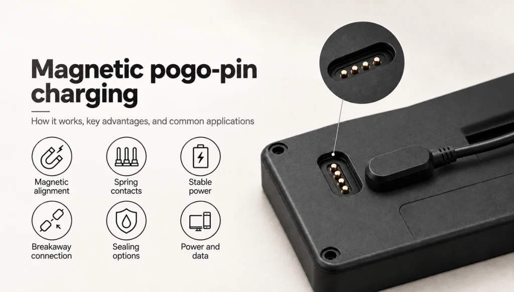
- How the charging contacts operate
- Five possible design benefits
- Magnetic contacts, USB-C and induction compared
- Potential docking applications
- Specification and validation checks
- Assessing fit for your device
A magnetic pogo-pin charging interface uses spring contacts for conductive power transfer and magnets for guided engagement and retention. Extra contacts can serve data, detection or control where the pinout and electronics support them. The contact assembly is part of the charging system, not the battery-control circuit itself.
magnetic spring-contact charging interfaceUnlike induction, this mechanism uses physical electrical contact. A suitable design can offer compact packaging, guided connection and manageable removal for frequently docked wearables, medical equipment, glasses, handheld products or industrial devices, subject to their actual validation requirements.
How the charging contacts operate
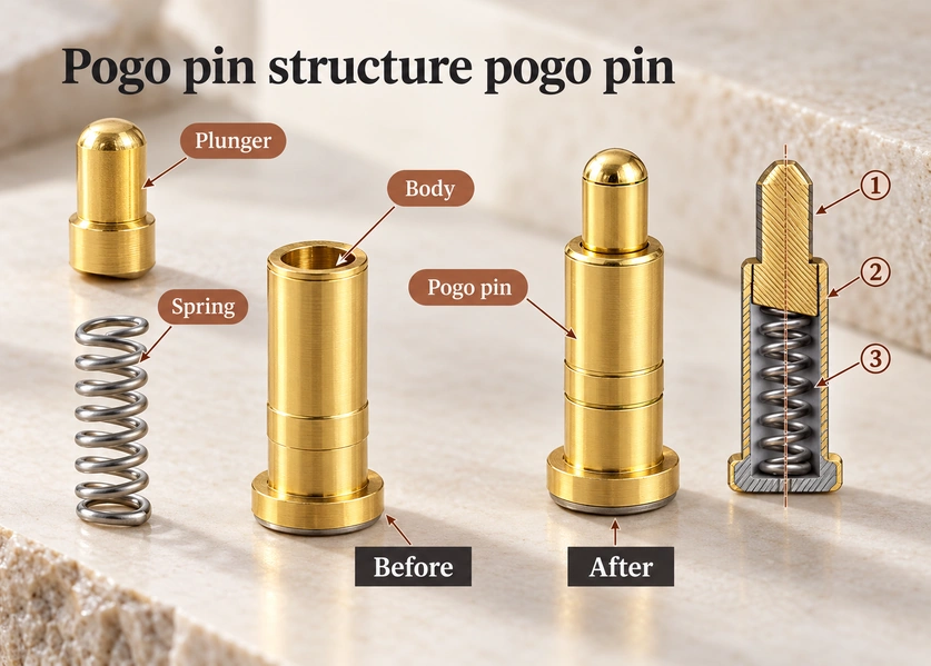
The mating pair typically consists of spring contacts at the charger and matching contacts or pads at the device. The complete charging path also includes the appropriate electronics.
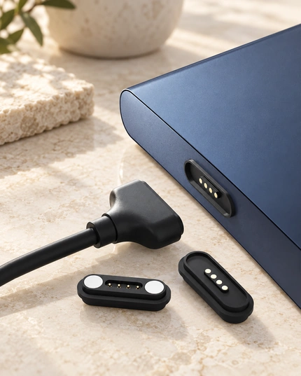
Magnetic attraction assists placement without conventional plug insertion. Descriptions such as “zero insertion force” refer to that engagement method; spring compression, holding and separation still involve forces that must be designed.
The pins press against their matching surfaces within the specified working travel. This accommodates limited axial variation while maintaining the required pressure, with lateral alignment controlled by the housing.
One power path is:
Power supply → magnetic cable → spring contacts → device pads → charging controller → battery
A two-contact example can assign one positive power path and one return. Charging detection and protection still depend on the system design.
two-contact charging interfaceOther contacts may serve:
Power
Ground
Data
Device detection
Charging control
ID signals
A suitable pinout can provide power and data together, but neither is guaranteed merely by adding contacts.
The battery-management and charging electronics set voltage, current, protection and charging behaviour. Spring pins provide the conductive mechanical interface; they do not implement the charging algorithm.
Five possible design benefits
The mechanism offers packaging and pin-assignment options as well as a different attachment action. Charging speed comes from the complete power design, rather than from the magnets.
1. Guided magnetic engagement
Magnets can guide the halves together within a defined capture range, reducing the need to insert a plug into a small socket. The housing and polarity must establish the correct final alignment.
Magnet-assisted mating can avoid conventional insertion resistance. It still needs enough force for the contacts’ permitted compression and a suitable release effort.
This can help frequent charging of small devices or products intended to be easy to handle, including for older users. Assess the actual handling experience; it is not an accessibility test result.
2. Surface connection and removal
The contacts meet at mating surfaces rather than requiring a deep conventional socket. Sealing and mechanical support remain separate design requirements.
Spring-contactSpring compliance can suit repeated engagement where the assembly has limited axial variation. A handheld charging cradle is one possible application, with its actual life target verified by testing.
3. Custom packaging
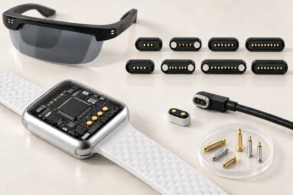
A contact assembly can be developed around the device’s available envelope.
Design inputs include:
Contact count and pitch; connector length; working height; contact layout; retention and release force; PCB mounting; cable exit
PCBConsider a custom assembly where a suitable standard receptacle cannot meet the enclosure or docking requirements.
4. Controlled breakaway
A magnetic joint can separate when the applied load overcomes its retention. Measure the relevant force and direction rather than assuming release will always prevent device movement.
Docks and portable products can benefit from that behaviour where accidental cable pulls are relevant. The device weight, support and dynamic loading still need assessment.
5. Combined power and signal paths
Assign the available contacts to the required functions and return paths.
For example, a five-contact allocation could be:
| Pin | Example Function |
|---|---|
| Pin 1 | Power |
| Pin 2 | Ground |
| Pin 3 | Data |
| Pin 4 | Data |
| Pin 5 | Detection / ID |
Scroll horizontally to view every column.
This is an example, not a universal pinout. Four or five contacts do not automatically support USB; the protocol, current path and contact assignments must be designed for the actual device.
USBMagnetic contacts, USB-C and induction compared
Compare each architecture against compatibility, packaging, guided docking and contactless-transfer priorities. No single approach covers every device requirement.
| Feature | Magnetic Pogo Pin Charger | USB-C | Wireless Charging |
|---|---|---|---|
| Connection | Magnetic physical contact | Plug and socket | Contactless |
| Electrical contact | Yes | Yes | No |
| Alignment | Magnetic guidance with defined housing geometry | Manual insertion | Coil positioning, with magnetic assistance where implemented |
| Custom size | Contact and housing layout can be tailored | USB mating geometry follows the applicable standard | Requires charging coil |
| Frequent docking | Suitable where the mating-life and docking requirements are validated | Requires insertion and the specified port life | Requires appropriate positioning and controls |
| Power + data integration | Requires a suitable pinout, signals and return paths | Depends on the implemented USB functions and cable | Power-control communication differs from application data |
| Breakaway connection | Possible; validate release force, direction and device support | Generally no | The device can be lifted from the transfer surface; this is a different release mechanism |
| Universal compatibility | Typically a dedicated matching interface | Standard connector form; source, cable and device functions must match | Only within the implemented compatible wireless system |
| Best suited for | Dedicated devices | General electronics | Contactless charging |
Scroll horizontally to view every column.
USB-C comparison
USB-C provides a standardized connector form. USB Power Delivery can reach up to 240 W with the required compatible source, cable and receiving equipment. That is a conditional standard capability, not the rating of every USB-C port or a Magtor magnetic contact design.
Standardized negotiation and matching implementations can support interoperability, while actual device and cable capabilities must still agree.
A magnetic spring-contact pair is generally a dedicated interface developed for the product’s mechanical layout and electrical functions.
A wearable, medical device or other compact product may prioritise that custom fit, subject to its own safety and compatibility requirements.
The design emphasis differs:
USB-C uses a standardized mating interface; a custom magnetic assembly is developed around a dedicated product and docking action.
Inductive charging comparison
Magnetic attachment and inductive power transfer are different mechanisms.
inductive power transferHere, metal contacts carry current while magnets assist guidance and retention.
In Qi induction, an alternating transmitter-coil field induces a voltage at the receiver coil. The associated electronics control the transfer.
Qi2 MPP also uses magnets to assist coil alignment, while the power still crosses through induction. Magnetic positioning is therefore not exclusive to pogo-pin interfaces.
As a conceptual distinction:
Magnetic spring contacts: magnets for guidance, conductive contacts for power
Induction: coupled magnetic field for power, with the required control electronics
Potential docking applications
Consider the mechanism where a compact envelope, repeated docking, guided engagement or a dedicated pinout is useful. Quick attachment does not itself mean fast charging.

Examples include:
Wearables: Watches, trackers, rings and other small products can use a contact area tailored to their enclosure, with the full charging and environmental requirements assessed.
Hearing aids and medical equipment: Guided placement and a custom contact layout may help packaging and handling. Confirm device-specific safety and compatibility rather than assuming a universal charger.
Smart glasses and head-mounted products: A slim enclosure can make a conventional port difficult to fit; assess contacts, magnets, terminations and seals as a complete assembly.
Handheld and industrial devices: Scanners, terminals and measurement instruments can use guided contact docks, validated for their specified loads and exposures.
Robotic docks: Contacts can support recharging at a defined position, with navigation accuracy, capture range, compression and power control assessed separately.
Repeatedly connected cradles are a possible use for compliant contacts; the application still determines the required life and validation.
Specification and validation checks
Choose from the complete interface requirements rather than pin count alone.
Define voltage and continuous or peak charging current, then check contact dimensions, resistance, conductors and thermal behaviour for that load in the installed assembly.
Allocate the required functions. Power-only may use two contacts; charging with detection or communication can need four, five, six or more, according to the actual circuit and return paths.
Mechanical and environmental inputs include:
Count and pitch: Include each power, return and signal path with suitable spacing.
Height and travel: Keep each spring contact in its recommended working range at all permitted tolerances.
Retention and release: Maintain the required engagement without making intended removal difficult.
Resistance: Define acceptable initial and aged values, voltage drop and temperature rise.
Finish: Select plating for the specified wear, corrosion and environmental conditions.
Mounting: Consider SMT, through-hole, wire termination or a custom structure against the PCB and housing.
Exposure: Assess sweat, rain, dust and cleaning fluids for both the exposed contacts and enclosure seals. Ingress and chemical corrosion requirements are separate.
Validate the representative assembly under the actual load, geometry and environment; nominal electrical values alone are insufficient.
Assessing fit for your device
A magnetic spring-contact interface is worth evaluating where guided attachment, repeated charging, compact packaging or a dedicated power-and-signal layout meets the product requirements.
Consider USB-C where the applicable standardized interface and power negotiation are priorities. Consider induction where removing exposed mating power contacts matters. Confirm the actual compatibility and system requirements for either.
A custom magnetic assembly combines a conductive path with guided placement. The resulting efficiency, simplicity and thermal behaviour depend on the complete design and its validation.
For wearables, medical equipment, smart products, industrial devices or docks, review contact count, current, working height, force, seals, mounting and cable together. Application categories do not establish certification or a tested configuration.
Magtor can discuss custom magnetic spring-contact pairs and cables for the device structure and electrical requirements. Define the application, current paths, pinout and available space early to support an integrated design review.
Frequently asked questions
What determines the allowable charging current?
Current depends on contact size and resistance, finish, cable and thermal design. A small-wearable example may use 1–2 A, but that is not a universal model rating. Confirm the proposed current through voltage-drop and temperature-rise tests under the actual load.
Can the interface fit a custom device?
Contact count, pitch, dimensions, working height, force targets, mounting, cable length and exit direction can be tailored. Confirm feasibility and the assembled tolerances before adopting the design.
How can polarity and shorting risks be controlled?
Magnet-polarity keying, asymmetric housing, recessed contacts and suitable circuit protection can reduce risks. Verify that permitted mating angles and partial engagement cannot create unacceptable power connections; these features do not eliminate every possible fault automatically.
Can a magnetic charging interface be waterproof?
It can form part of an ingress-protected or sweat-exposed design. Specify seals, finish, ingress conditions and corrosion tests for the actual environment. An IP result does not automatically establish salt-spray or sweat resistance.
What information supports a custom design?
Provide voltage and current, contact count and functions, dimensions, mounting, retention and release targets, ingress requirements, cable details and device drawings. These inputs support the structure, material and validation review.