
How AI Smart Glasses Charge: Choosing the Case and Contact Interface
Published on August 7, 2026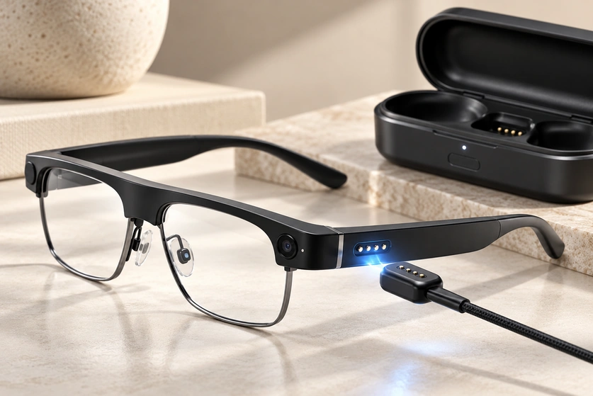
- Power and charging inside smart glasses
- Charging cases and magnetic cables
- Using spring contacts in a small frame
- Why move the USB-C port to the case?
- Magnetic contacts compared with direct USB-C
- Selecting two, four or more contacts
- Choosing the interface location
- Electrical and mechanical design checks
- Customising the interface around the frame
- Charging-interface support from Magtor
- Choosing a suitable charging architecture
Charging for AI smart glasses must fit the frame without making everyday use awkward. This guide reviews charging cases, USB-C inputs and magnetic spring contacts, then considers size, wear, sealing, current requirements and the design inputs needed to choose an interface.
spring-contact interfacesPower and charging inside smart glasses
A typical design uses a small rechargeable lithium battery in one or both temples. External power reaches that battery through the charging interface and the device’s battery-management and charging circuit, rather than connecting directly to an uncontrolled bare cell.
A typical power path is:
External supply → cable or charging case → mating contacts → charging and battery-management circuit → battery
USB-C can supply the external case or charger even when the glasses use a different, smaller contact interface.
Ray-Ban Meta provides one product example: the glasses sit in their dedicated case, with metal charging connections at the nose-bridge area. The case receives external power through USB-C. This describes that product’s arrangement, not a supply or compatibility relationship with Magtor.
Even Realities also uses dedicated cases with an internal battery and a Type-C input. Its G1 guide calls the interfaces “wireless charging contact surfaces”, while the G2 guide explicitly describes metal contacts. Keep those model descriptions separate rather than assuming that both use the same internal spring-contact construction.
Moving the conventional external charging input to a case can free space on the glasses frame.
Charging cases and magnetic cables
There is no single charging interface for every pair of AI glasses. Frame dimensions, battery capacity, ingress requirements, industrial design and product positioning influence the architecture.
1. A dedicated charging case
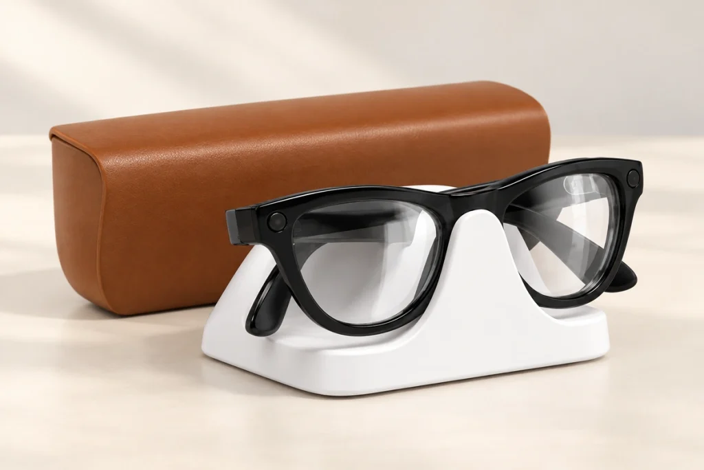
A charging case is one available approach for compact smart glasses.
The glasses are placed or folded into the case at the specified position so that the matching charging interfaces engage. Mechanical guidance and correct placement remain important.
The case combines two roles:
Protecting and storing the glasses
Recharging the internal battery
A case may have its own battery for recharging away from a wall supply. The number of recharges depends on usable case capacity, the glasses battery and conversion losses; it is not a fixed property of every case.
Ray-Ban Meta and Even Realities provide examples of case-based charging, with the model-specific interface differences noted above.
Ray-BanMetaThe frame can use a small charging area instead of accommodating a complete USB receptacle. The contacts, magnets, terminations and seals still take space and must be included in the mechanical design.
2. A magnetic charging cable
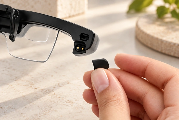
Another option brings a magnetic charging cable directly to an interface on the glasses.
magnetic charging cableA typical cable-end module contains:
Permanent magnets
Pogo pins or spring-loaded contacts
Plastic insulating housing
Cable assembly
The frame carries matching conductive contacts, positioned according to the mating drawings.
The magnets assist approach and retention while the compressed spring contacts establish the electrical path. Correct polarity, alignment and working travel are necessary for charging.
The intended sequence is:
Cable approaches → guided alignment → contacts engage → charging control permits power
Engagement can avoid guiding a conventional plug into a small port, but it still needs adequate contact alignment.
For a compact wearable, that can make the charging action easier when the mechanical design supports it.
Using spring contacts in a small frame
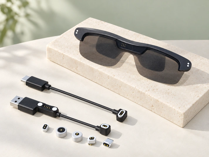
A pogo pin is a spring-loaded electrical contact that compresses against its mating surface.
A flat contact interface need not use a conventional deep receptacle. Designers can consider the temple, hinge, nose bridge or dock location, while allowing enough room for the spring-contact assembly, wiring and seals.
USB-CAssess the whole contact mechanism when comparing its space requirement with a conventional port.
Within the recommended working travel, the spring accommodates a limited amount of axial dimensional variation between charger and frame.
Spring pressure maintains contact over that permitted range. It does not eliminate the need for controlled alignment, working height and retention.
Potential design benefits include:
Compact charging interfaces
Guided engagement without seeing the contacts, where geometry permits
Reduced conventional insertion wear, with contact wear still assessed
Flexible connector geometry
Cleaner industrial design
Integration with charging cases or docks
Why move the USB-C port to the case?
Direct USB-C charging can be appropriate, but installing its receptacle in a slim frame creates space, handling and sealing questions.
First, account for the available space.
Depending on the model, the temples may contain batteries, speakers, microphones, antennas, processors, cameras, PCBs and structural parts. A USB-C receptacle adds its own volume, board footprint and mounting requirements.
Second, consider the charging action.
A daily charging routine may involve repeated plug insertion. A contact-based case or dock can instead let the user place the glasses at a defined position, provided the interface is guided and retained correctly.
Third, review the enclosure seals.
A conventional port opening needs an appropriate sealing design. A contact interface changes the enclosure arrangement, but contact penetrations and cable or rear interfaces must also be sealed. Neither approach is automatically waterproof.
A case-based design can therefore separate these two paths:
USB-C → Charging Case
Charging Case → Small Charging Contacts → Smart Glasses
The case accommodates the standardized USB input, while the frame uses a dedicated charging interface sized for its available space. Compare actual assemblies rather than assuming every contact interface is smaller.
Magnetic contacts compared with direct USB-C
| Feature | Magnetic Pogo Pin Charging | Direct USB-C |
|---|---|---|
| Connector size | Can be tailored to a compact frame | Allow for the selected receptacle and mounting footprint |
| User alignment | Magnetic guidance plus mechanical alignment | Manual insertion |
| Charging case integration | Can be integrated into a purpose-designed case | Possible; depends on case geometry and plug access |
| Design flexibility | Contact count and housing can be customised | Standardized geometry |
| Frequent connection | Validate the required daily-use cycle life | Mechanical insertion required |
| Waterproof design | Contact penetrations and rear interfaces still require seals | Port sealing required |
| Power + data | Requires a suitable pinout, return paths and electrical design | Depends on the port, cable and implemented functions |
| Interoperability | Typically a device-specific mating interface | Standardized connector form; functions and compatibility must match |
Scroll horizontally to view every column.
USB-C can be useful at the case or dock input, while a custom spring-contact interface can suit the frame. Select both according to the actual device, power and packaging requirements.
The two interfaces can form different parts of the same charging system.
Selecting two, four or more contacts
Choose the contact count from the power, return, control and communication functions that must cross the interface.
2 Pin Magnetic Connector
2 Pin Magnetic Connector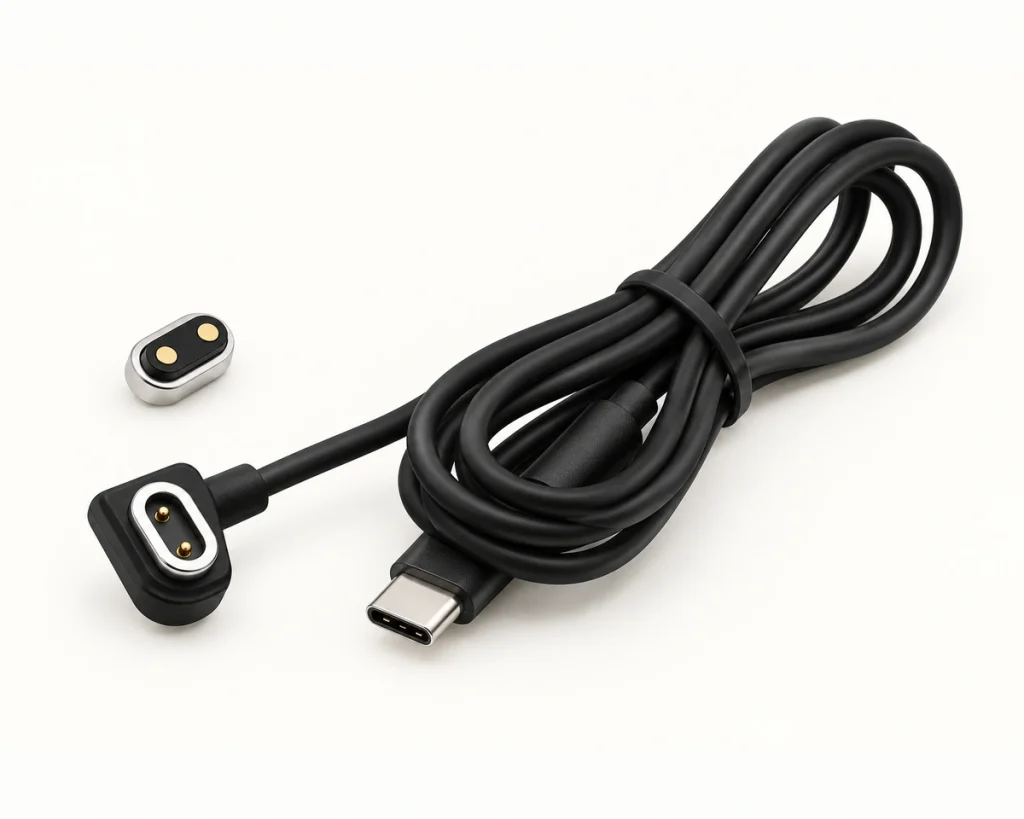
A charging-only interface may use two contacts, for example:
| Pin | Example function; confirm the actual mating drawing |
|---|---|
| Pin 1 | VCC / Positive |
| Pin 2 | GND / Negative |
Scroll horizontally to view every column.
Two contacts can provide a compact charging-power interface where positive and return are the only required functions. Polarity, charge control and protection still need to be designed.
Magtor offers two-contact magnetic designs for compact wearable charging applications. Magnets assist alignment and spring contacts conduct power; verify the particular design against the glasses’ requirements.
4 Pin Magnetic Connector
4 Pin Magnetic ConnectorWhen charging also needs communication, identification, detection or another electrical function, a four-contact arrangement may be worth evaluating.
One possible allocation is:
VCC
GND
DATA+
DATA− in a differential pair, or a separate ID function in a different architecture
Use the actual circuit and both mating-view drawings to define the pinout. Assignments are not universal, and replacing a differential DATA− contact with ID changes the communication architecture.
Four-contact Magtor designs can be considered where the interface needs power and basic signals, with the electrical functions specified for the project.
5 Pin or Multi-Pin Magnetic Connector
A more complex interface may need contacts assigned to:
Power
Ground
Communication
Device identification
Charging control
Diagnostics
Firmware or factory testing
Five or more contacts may suit these requirements. The list describes possible functions, not a promise that five pins carry all seven independently.
Use enough contacts to meet the requirements reliably, including the necessary grounds and return paths. Adding contacts without a defined purpose does not establish better performance.
Choosing the interface location
Four locations to consider are:
Temple
Contacts near the temple end or side can be accessible to a magnetic cable while staying clear of the main optical area. Check the actual frame, wiring and user access.
Hinge Area
The hinge can conceal the interface, but movement, clearance, wiring flex and available space need particular attention.
Nose Bridge
A case can locate charging contacts near the nose bridge, provided the glasses and case are guided to the correct mating position.
The Ray-Ban Meta nose-bridge charging arrangement is one model-specific example.
Charging Case or Dock
Alternatively, define the interface as part of a dedicated dock.
The user places the glasses at a specified position; housing features and, where used, magnets then guide the contacts into alignment.
A well-guided dock can make a daily charging routine straightforward.
Electrical and mechanical design checks
Appearance is only one selection input. Review six electrical, mechanical and environmental areas during development.
Current and Voltage
Specify the maximum charging current and working voltage, with the required protection and model-specific ratings.
Also check contact resistance, full-load voltage drop, temperature rise and charging behaviour in the assembly. A nominal current number alone cannot establish suitability.
Connector Size
Small dimensional changes can matter in a crowded frame.
Review connector width and height, contact diameter and pitch, magnet dimensions and PCB footprint together with the enclosure, terminations and support structure.
A custom layout is one option where a standard part does not fit those constraints.
Contact Resistance
Stable, low contact resistance helps limit resistive loss and voltage drop.
Check resistance at initial assembly and after the specified mating, environmental and contamination tests. Set appropriate acceptance limits for the application.
Magnetic Force
Balance retention with removal effort. The installed interface must stay engaged without making the charger awkward to release; magnet attraction and actual pull-off force are different measurements.
The target depends on:
Connector dimensions
Product weight
Charging orientation
Number of contacts
Dock structure
User interaction
Mating Cycles
Estimate daily charging frequency over the intended product life when setting the cycle target.
Lifecycle testing should track spring fatigue, contact and plating wear, contamination and resistance change under the specified working height and load.
Sweat and Moisture Resistance
On the head, the frame can encounter sweat, humidity, rain, cosmetics, dust and skin oils. Define the relevant exposures for the intended use.
Ingress protection and chemical corrosion resistance are separate requirements. A water seal alone does not demonstrate resistance to sweat.
Assess seals, housing interfaces, plating and materials together, with application-specific acceptance tests.
Customising the interface around the frame
In a lightweight integrated frame, the charging interface needs to be planned with the surrounding components. Standard parts remain possible where they meet the same constraints.
A part only a few millimetres beyond the available envelope can interfere with the battery, PCB, hinge or speaker; check the actual stack-up.
A custom spring-contact assembly can be shaped around the frame instead of requiring the enclosure to accommodate a fixed receptacle. Compare that option with suitable standard components.
Project-specific design variables include:
Pin count
Pin pitch
Connector dimensions
Magnetic polarity
Magnetic force
Contact plating
Housing shape
PCB mounting method
Cable outlet direction
Waterproof structure
Charging dock interface
This flexibility can be useful where wearable packaging is tightly constrained, provided the final electrical and mechanical design is validated.
Charging-interface support from Magtor
Magtor can discuss custom magnetic spring-contact interfaces for charging cables, cases, docking stations and other compact wearable assemblies. Specify the mating arrangement and operating requirements for the project.
MagtorA two-contact arrangement can supply positive and return in a compact charging-only interface, with correct polarity and charge protection.
For combined charging and communication, consider four, five or more contacts against the defined pin functions, return paths and mechanical envelope.
Dimensions, magnetic force, contact allocation, housing geometry, cable construction and sealing can be tailored for the project. Compact wearable designs must account for available space, repeated charging, sweat exposure and guided alignment. This does not imply supply to the third-party products discussed in this guide.
magnetic spring-contact interfaceBring the charging interface into the OEM or ODM mechanical review early, before the frame layout is fixed. That leaves room to resolve contacts, routing, mounting and seals together.
Provide these starting requirements:
Operating voltage; charging current; contact count and functions; available space; retention and release-force targets; ingress requirements; mounting method; expected mating cycles
These inputs give the design review a basis for matching the interface to both the electronics and the frame.
Choosing a suitable charging architecture
No single charging method fits every smart-glasses product.
Where a common external supply interface is useful, USB-C can power the case or dock, subject to the chosen port, cable and power implementation.
Where the frame needs a dedicated compact connection, magnetic spring contacts offer options in size, shape, alignment and appearance. Sealing requires an appropriate structure and validation.
One combined architecture is:
USB-C supply → charging case → magnetic spring-contact interface → smart glasses
This keeps a common USB-C supply connection at the case while reducing the need for a complete USB receptacle on the frame.
Conclusion
Dedicated cases, conductive contacts and magnetic cables are possible charging approaches for AI glasses. The chosen arrangement depends on the product; third-party examples do not establish a Magtor supply or compatibility relationship.
Balance electrical requirements with space, wear life, ingress protection and the user’s charging routine as the frame design develops.
Two contacts may cover charging power alone. Four, five or more can support additional signals where the pinout, return paths, circuit and protections have been designed for them.
For a custom charging cable, case or dock, contact Magtor with the available frame space and electrical requirements. The interface can then be assessed as part of the complete wearable design.
contact MagtorRelated design guides