
Why Wearable Charging Interfaces Are Often Device-Specific
Published on September 9, 2026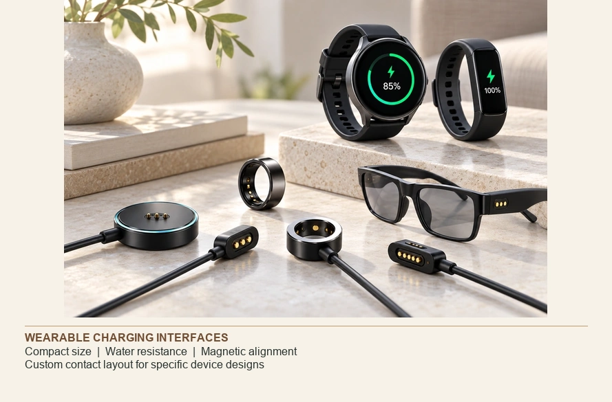
- Defining a Device-Specific Charger
- Wearable Shape and Interface Integration
- The Device-Side USB-C Trade-off
- Compatibility of Magnetic Chargers
- Customization and Replacement Trade-offs
- Differences Between Watch Accessories
- Standardization and Its Current Scope
- Magnetic Contact Charging for Wearables
- Specifying a Wearable Interface
A wearable charger can be specific to its size, housing, sealing requirements, magnetic alignment, contact layout and circuitry. Watches, fitness trackers and rings may therefore have a custom device interface while using USB-C at the power-source end.
Dedicated charging interfaces can reflect mechanical integration requirements as well as ecosystem decisions. A particular manufacturer's motives require evidence beyond the connector design.
Defining a Device-Specific Charger
A proprietary wearable interface serves a particular product or family rather than providing a standardized device-side connection such as USB-C.
USB-CExamples include magnetic cables, pogo contact chargers, charging pucks, ring docks and cradles. Some of these categories overlap.
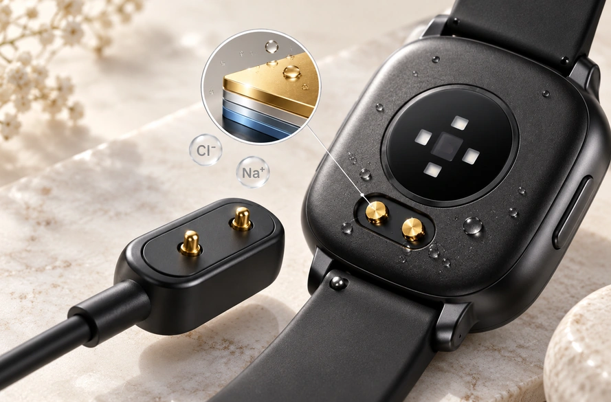
Keep the adapter end distinct from the wearable end. the device manufacturer’s specified reference smartwatch accessories, for example, combine a device-specific magnetic pin connection with USB-C at the source; compatibility is defined for the listed models.
A custom device connector can still receive power through a standardized upstream USB connection, with source and device requirements matched.
Wearable Shape and Interface Integration
Wearable products encompass a wide range of shapes and layouts.
Watches may be round or rectangular, trackers narrow, and rings may have little flat space for a plug. Sensors, batteries, antennas and skin-contact areas compete for that limited room.
These constraints make charging part of the mechanical architecture in many designs.
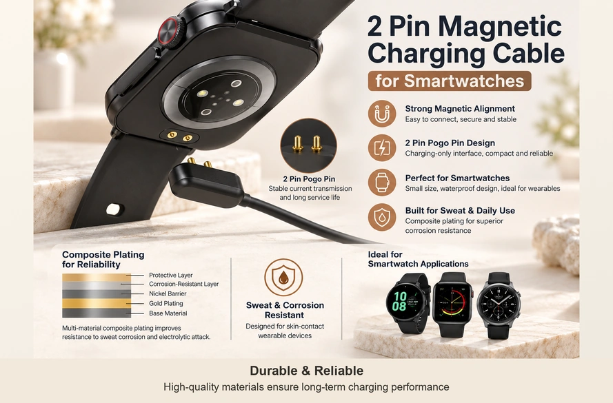
A dedicated interface lets the design team place contacts, set thickness and retention force, and shape the housing around the product instead of accommodating a fixed plug arrangement.
That flexibility can matter where space is scarce or the external charging surface must stay low-profile. Internal contacts, coils or seals still need their allocated volume.
The Device-Side USB-C Trade-off
USB-C offers a standardized power-and-data framework, with capabilities defined by implementation. Its receptacle still needs installation space, support and a housing opening.
A small wearable can leave the larger head or dock structure off the device and expose only compact mating pads, where the product design supports it.
For example, a magnetic pogo design can put pins, magnets and the cable housing on the charger, with a small matching pad area on the wearable.
pogo pinUSB-C can still suit a wearable. Assess its physical receptacle against size, sealing and industrial-design requirements.
Compatibility of Magnetic Chargers
Magnetic interfaces depend on both mechanical geometry and electrical specifications.
Two-contact heads can be incompatible even when they have the same contact count.
Check these compatibility factors together:
Pin pitch, electrical polarity, magnetic polarity, voltage, current, pogo working height and housing dimensions.
As an example, one two-contact layout may place V+ on the left when viewed from a specified direction, and another may reverse it. Equal pitch also does not ensure matching magnet orientation or compression.
The Magtor 2 Pin Magnetic Charging Cable range illustrates configurable pitch, polarity, terminations and dimensions for OEM integration.
2 Pin Magnetic Charging Cable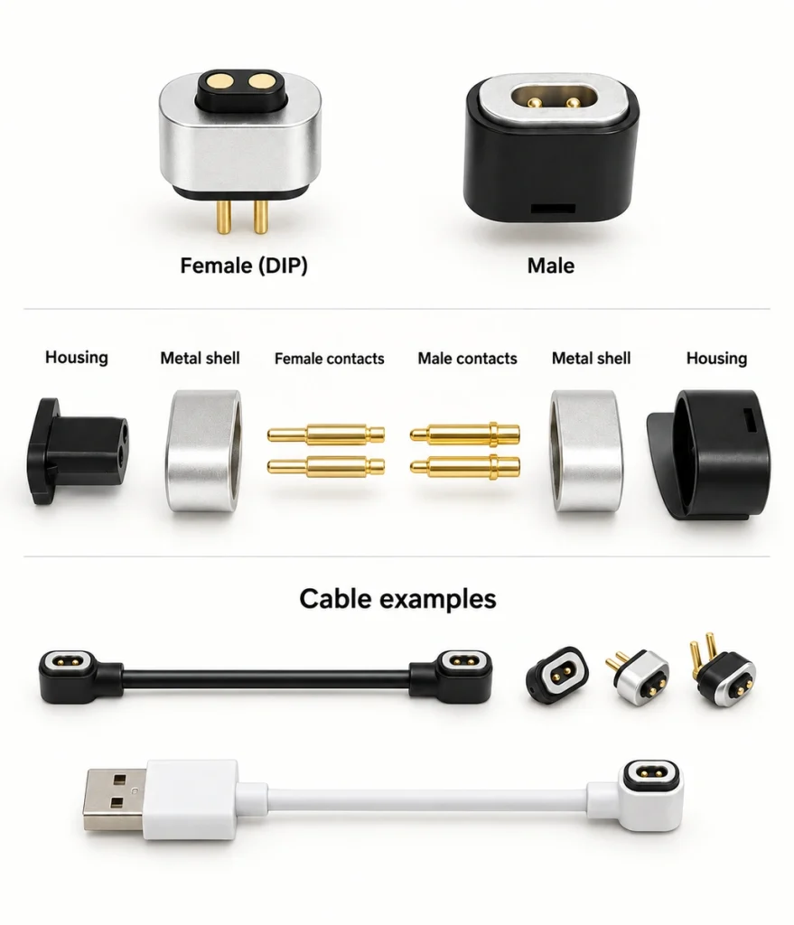
The guide Are Two-Contact Magnetic Cables Interchangeable? explains why contact count alone is insufficient for compatibility.
Are 2 Pin Magnetic Charging Cables UniversalThese matching requirements help explain why many magnetic wearable interfaces remain product-specific.
Customization and Replacement Trade-offs
A dedicated interface allows closer integration with the device, while introducing trade-offs in replacement and compatibility.
| Design opportunity | Compatibility or service consideration |
|---|---|
| Compact device-side interface | May fit only one product family |
| Accommodation of unusual wearable shapes | Replacement may be less convenient |
| Guided magnetic alignment | Limited cross-brand compatibility |
| Custom contact count and pitch | Users may need several chargers |
| Assigned power, ID or signal paths | More accessory variations |
| Interface designed for enclosure sealing | Dedicated parts may add complexity |
Scroll horizontally to view every column.
Customization offers design flexibility; accessory fragmentation can add a burden for users.
For an OEM product, weigh compact integration against replacement convenience and broadly compatible charging accessories.
Differences Between Watch Accessories
Watch-side interfaces vary between product families and generations. Some accessories support several specified models, while others do not.
A reference smartwatch family uses magnetic pin-to-USB-C chargers for two earlier models and quick-charge docks for later models. Some accessories support more than one model, illustrating why the exact accessory and supported-model list matter.
Other smartwatch families specify magnetic flat docks for particular models. A magnetic dock description does not by itself identify a pogo contact power path.
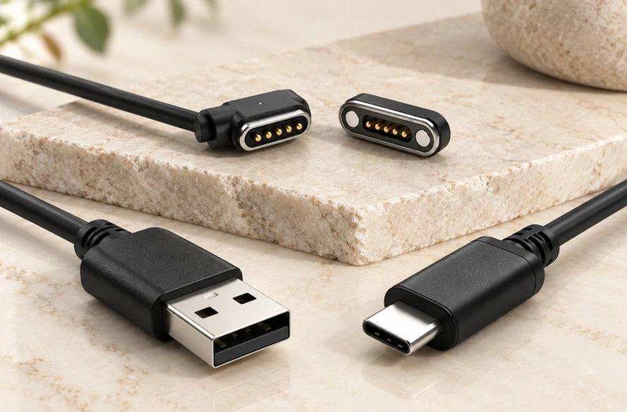
The examples show a possible pattern:
Power-source connection: increasingly standardized. Wearable connection: often still product-specific.
Type-C can reduce variation at the source end without replacing every magnetic or spring-contact interface on the wearable.
Standardization and Its Current Scope
Charging standardization is developing, while the scope for wearable categories remains a separate question.
As of 8 October 2026, the EU common-charger information lists categories including smartphones, tablets, earbuds, cameras, keyboards and mice, with laptops covered from 28 April 2026. Smartwatches are outside that current mandatory category list; this is a summary of scope, not a product compliance assessment.
The European Commission's 30 June 2026 report examined smartwatches, fitness trackers, smart glasses and wristbands among potential future categories. Examination of those categories does not itself add them to the requirements.
For the wearables studied, the report's 2023 sample recorded USB Type-C adoption at about 6%, or 4 of 63 products. It suggested that size and form may explain dedicated connectors, pads, cases or boxes, and noted USB-C inputs on some newer pads or cases. The figure describes that sample, not current global sales.
One possible direction inferred from these examples is:
USB-C may standardize more charger inputs while the device-side connection remains magnetic, inductive or specific to the product.
The accessory examples above already demonstrate mixed source-side and wearable-side architectures.
Magnetic Contact Charging for Wearables
Conductive magnetic docking offers features that can suit small wearables.
Magnets guide the head, and physical pogo-to-pad contact conducts power. This can leave a small external mating area without a conventional plug extending into the housing.
For charging alone, one possible contact assignment is:
Pin 1 → V+. Pin 2 → GND.
Further paths may serve identification, communication or control when the complete electrical design supports them.
The guide Designing a 2 Pin Magnetic Charging Cable for a Smartwatch covers pitch, polarity, magnetic force and contact design for watch integration.
SmartwatchesSweat and moisture still affect exposed contacts. Reducing Corrosion Risk at Wearable Charging Contacts explains plating, contact pressure and electrolysis resistance for skin-contact electronics.
How to Prevent Charging Contact Corrosion in Wearable DevicesSpecifying a Wearable Interface
Begin with product requirements before choosing an interface type.
Two paths may suit V+ and GND for charging alone. Data, ID detection or control may require further contacts, assigned together with the device circuitry.
Confirm five groups of requirements:
Electrical: voltage, current, polarity and signal assignments.
Mechanical: pitch, dimensions, working stroke and housing space.
Magnetic: alignment direction, magnet polarity and retention force.
Environmental: sweat exposure, corrosion resistance, sealing and required mating cycles.
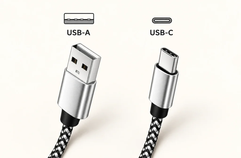
Cable: USB-A, USB-C, bare wire or terminal connection, along with length and outlet direction.
A custom Magnetic Cable Connector can pair the device-side magnetic interface with USB-A, USB-C, terminal wires or another termination according to the product architecture.
The Magnetic Cable Connector Selection Guide expands the checklist to contact count, current, voltage, length, gauge, force and environment.
How to Choose a Magnetic Cable Connector for Your DeviceStandard Input, Product-Specific Docking
A wearable-specific interface can address its combination of size, geometry, sealing, contact layout and electrical demands.
The source connection can still be standard USB-C while the wearable uses a custom magnetic, pogo contact or dock interface. Compatibility depends on the specified components and electronics at both ends.
Choose the interface within the complete product architecture and verify mating and replacement compatibility.
Charging-only products may use a compact two-contact cable. For data, identification or control, assess a multi-contact Magnetic Cable Connector with the appropriate paths and electronics.
Magnetic Cable ConnectorOne possible path toward more standardized charging is a common USB-C input with the final watch, ring or tracker connection tailored to its product. It remains a design direction, rather than a requirement to put a Type-C socket in every wearable.