
Selecting a 2 Pin Magnetic Charging Cable for Your Device
Published on August 31, 2026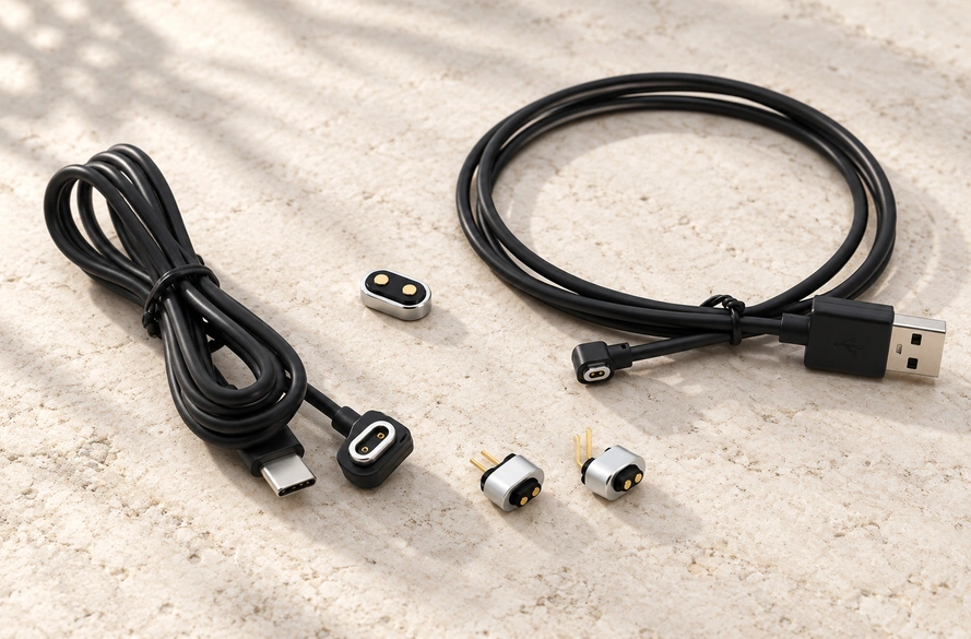
- Understanding the Two-Contact Cable
- How Magnetic Contact Charging Works
- Cable and Head Configurations
- Specifications to Check
- Checking Charger Compatibility
- Selecting a Cable for the Device
- Typical Two-Contact Applications
- Integration Faults, Validation and Customization
A 2 pin magnetic charging cable combines two conductive contacts, usually power and ground, with magnets that guide alignment and retain the connection. Check pin pitch, electrical and magnetic polarity, voltage, current, dimensions and pin working height before using it: two-contact magnetic chargers are not all interchangeable.
2 pin magnetic charging cableMost two-contact magnetic cables are device-specific. Their pin spacing, two types of polarity, voltage, current, connector dimensions and pogo working height must match. Review these details both when replacing a cable and when developing a custom charging interface.
Understanding the Two-Contact Cable
This cable assembly links a power source to the product through a magnetic interface with two electrical contacts.
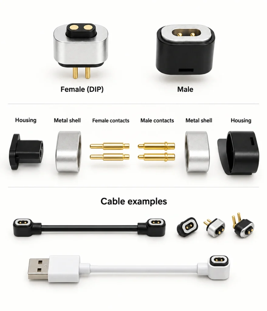
A basic DC design generally assigns one device-side contact to V+ and the other to GND. Magnets around or beside the contacts help move the cable head into its mating position.
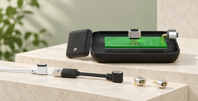
Many versions use spring contacts in the cable head and flat pads on the product. This arrangement is often called a 2 pin magnetic pogo pin cable.
The label “2 pin” specifies only the contact count. It does not establish dimensions, voltage, current, spacing or polarity.
Two apparently similar two-contact chargers may therefore be incompatible.
An assembly usually contains the power-source connector, conductors, an overmolded magnetic head, magnets, two contacts or pogo pins, and the matching device-side part. If only the connector is needed, refer to the standalone 2 Pin Magnetic Connector rather than the complete cable.
2 Pin Magnetic ConnectorHow Magnetic Contact Charging Works
The interface joins mechanical guidance with conductive charging.
Attraction guides the magnetic head toward its matching interface. After alignment, the spring contacts compress onto the pads, establishing the conductive path for charging.
Power follows this path through the assembly:
Power source → USB or wire input → conductors → magnetic head → pogo pins → device pads → charging circuit → battery.
Magnets chiefly guide and hold the mating parts. Pogo pins or other conductive contacts carry the electrical current.
Strong attraction alone does not establish good charging. High contact resistance, inadequate compression or incorrect electrical polarity can still disrupt the connection.
Magnetic docking can avoid repeated insertion into the housing. It may help frequently charged products or devices with insufficient space for a conventional receptacle.
The Magtor Magnetic Cable Connector range also includes other contact counts and cable assemblies for charging, signals or device detection.
Magnetic Cable ConnectorCable and Head Configurations
The same two-contact charging principle can be packaged in several cable configurations.
USB-A to Two-Contact Magnetic Cable
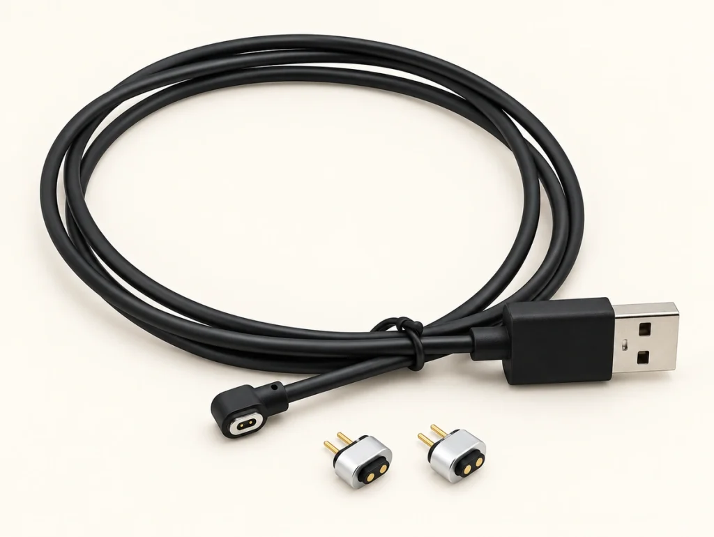
USB-A is used with many desktop adapters, charging docks, industrial products and existing USB power supplies.
For basic low-voltage charging, it can connect the magnetic interface to an established power-source layout.
USB-C to Two-Contact Magnetic Cable
This version places USB Type-C at the power-source end and a two-contact magnetic connector at the device end.
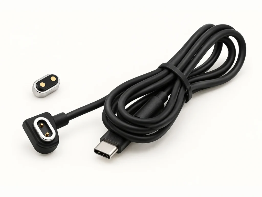
The compact reversible USB-C plug and widely available adapters make this configuration useful for new product designs.
Keep the connector format separate from its charging functions:
Using USB-C does not automatically give the magnetic cable USB Power Delivery or a particular fast-charging protocol.
USB Type-C defines the connector system. USB Power Delivery separately specifies power negotiation and related functions, so USB-IF maintains distinct documents: USB Type-C Cable and Connector Specification — USB-IF and USB Power Delivery Specification — USB-IF.
USB Type-C Cable and Connector Specification — USB-IFUSB Power Delivery Specification — USB-IFSpecify charging capability from the complete electrical design, rather than infer it from the plug shape.
Open-Wire and Terminal Ends
An industrial product, dock, embedded system or custom supply may not need a USB connection.
Bare wires, crimp terminals, PCB connectors or another custom end can instead integrate the cable into an existing harness or charging base.
Choosing Circular, Rectangular or Oval Heads
A circular head may suit a compact product, recessed port or sealed structure. Rectangular and oval layouts can offer more control of orientation, pitch, magnet position and the cable outlet.
Choose the head geometry to suit the enclosure's requirements.
Specifications to Check
Review the cable as a mechanical and electrical assembly. Matching the contact count alone is insufficient.
| Specification | Why It Matters |
|---|---|
| Voltage | Must match the device charging circuit and power architecture |
| Rated current | Determines whether the connector and cable can safely carry the required charging current |
| Pin pitch | Determines whether the two electrical contacts physically align |
| Electrical polarity | Ensures V+ and GND connect to the correct device contacts |
| Magnetic polarity | Determines whether the two halves attract and orient correctly |
| Contact resistance | Influences voltage loss, heat generation, and charging stability |
| Pogo pin working height | Determines whether sufficient contact pressure is maintained |
| Wire gauge | Affects current capacity and voltage drop |
| Cable length | Longer cables can increase resistance and voltage drop |
| Magnetic force | Affects connection stability and break-away behavior |
| Contact plating | Influences wear resistance and corrosion performance |
| Mating life | Important for products that are charged frequently |
| IP requirement | Important when the device is exposed to water, sweat, or dust |
Scroll horizontally to view every column.
Checking Contact Pitch
Measure pitch between the centers of adjacent contacts.
Even a small spacing mismatch can move a pin away from the center of its device-side pad.
Misalignment may reduce contact area, raise resistance, interrupt charging or prevent a connection altogether.
Confirm the actual center-to-center dimension for the product; two-contact cables do not all use the same pitch.
Separating Electrical and Magnetic Polarity
Treat electrical polarity and magnet orientation as different specifications.
Electrical polarity assigns positive voltage and ground to the contacts.
One illustrative assignment is:
Pin 1 → V+; Pin 2 → GND.
That example is not a universal pinout for magnetic chargers.
Magnetic polarity defines how the magnets are oriented.
A mismatched magnet orientation may repel the parts or permit the wrong docking orientation. Incorrect electrical polarity can leave a physically attached connector unable to charge safely.
Verify the two polarities independently in design and compatibility checks.
Checking Charger Compatibility
Most two-contact magnetic cables are not universal replacements.
Matching contact counts can conceal differences in the other essential specifications.
At minimum, assess the following compatibility factors together:
Pin pitch + connector dimensions + electrical polarity + magnetic polarity + voltage + current + pogo working height must be evaluated for the intended charging interface.
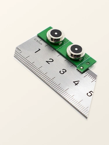
Correct pitch alone does not establish a match.
For example, two chargers may both have 4 mm spacing but opposite V+ and GND assignments. Another can have a different magnet orientation, or a working height that prevents proper pin compression against the pads.
A mechanical fit does not by itself confirm electrical compatibility.
Before powering a replacement cable, compare the original cable, device specifications, dimensions and polarity.
Define an OEM interface with controlled mechanical drawings and electrical specifications, rather than an existing commercial charger alone.
Selecting a Cable for the Device
Begin with the product's charging requirements before selecting the head shape.
Specify input voltage and maximum charging current. These requirements affect pin size, wire gauge, construction, contact resistance and temperature rise.
Next, allocate enclosure space for the head, magnets, contact spacing, insulation, seals and strain relief.
Set pin pitch and working height so fully docked pogo pins remain within their recommended compression range.
Define electrical and magnetic polarity separately. Where reverse attachment must be excluded, magnet placement and housing geometry can control the permitted orientation.
Select the power-source end for the product architecture. USB-A can suit existing supplies, USB-C may suit newer ecosystems, and wire or terminal ends may suit integrated stations or industrial equipment.
Assess wire gauge with length: a longer or thinner conductor adds resistance and may increase voltage drop under load, especially at higher current.
Define exposure before finalizing the layout. Rain, sweat, dust, cleaning fluids or outdoor use may require seals, corrosion-resistant plating, overmolding or a specified IP level.
IEC 60529 defines enclosure ingress-protection classifications; the IEC 60529 IP Code Standard provides that classification framework.
IEC 60529 IP Code StandardUse samples to validate the complete assembly. Check charging current, temperature rise, contact resistance, polarity, mating behavior, repeated connections, cable bending and the required environmental conditions.
Typical Two-Contact Applications
Two contacts can suit a device needing mainly power and ground, with no extra communication path through the same interface.
That arrangement is useful for compact rechargeable products.
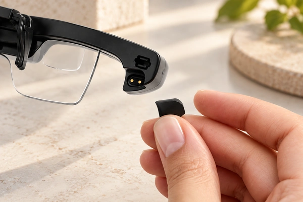
A wearable may use a small two-contact pogo cable so the user can dock the charger without precise manual plug insertion.
Hearing devices and other compact electronics may also use magnetic charging where space is limited and repeated connection is expected.
Other applications include smart-home products, sensors, pet trackers, portable instruments, beauty devices, electric toothbrushes and personal-care electronics.
Products exposed to water may use external magnetic contacts to avoid a deep charging receptacle. This can simplify some enclosures, but the complete device structure still determines water protection.
For an OEM project, go beyond whether the cable appears in the same industry and ask:
Does the product need only two charging contacts, and would magnetic docking address its mechanical, environmental or usability requirements?
Identification, temperature sensing, communication or data transfer may call for a 3 pin, 4 pin, 5 pin or higher-contact-count magnetic cable instead.
Integration Faults, Validation and Customization
Integration details account for many charging faults in a two-contact magnetic system; the magnetic principle alone does not explain them.
| Problem | Possible Cause | What to Check |
|---|---|---|
| Cable attaches but does not charge | Incorrect electrical polarity | Check V+ and GND assignments |
| Magnets repel | Incorrect magnetic polarity | Verify magnet orientation |
| Charging cuts in and out | Insufficient pogo compression or contamination | Check working height and contact surface |
| Charging is slower than expected | Voltage drop or current limitation | Check wire gauge, cable length, contact resistance and power source |
| Connector becomes warm | Excessive current or resistance | Measure current, resistance and temperature rise |
| Cable disconnects too easily | Magnetic force too low | Review magnet size, spacing and mechanical structure |
| Pins do not align with pads | Incorrect pin pitch or housing dimensions | Verify mechanical drawing |
| Performance declines after repeated use | Contact wear or corrosion | Review plating, environment and mating-cycle requirements |
Scroll horizontally to view every column.
Validate these requirements before tooling and high-volume cable production for a mass-produced device.
A custom cable can follow the existing product rather than require changes to its enclosure or PCB. Options may cover dimensions, pitch, pin diameter, working height, magnetic force, magnetic polarity, electrical polarity, length, wire gauge, USB-A or USB-C ends, open wires, overmolding, cable direction, plating and sealing structure.
Magtor two-contact magnetic cable configurations include USB-A, USB-C and bare-wire ends. OEM options can adapt length, polarity, dimensions and wire gauge to the project.
For a prototype, provide the device-side drawing, connector dimensions, pitch, voltage and current, electrical polarity, length, preferred source connector, environmental needs and expected mating conditions.
Those inputs let the cable be developed as part of the device's charging system.
Specifying a Compatible Charging Assembly
Two-contact magnetic cables can provide compact power connections for products needing only two charging contacts. Magnetic guidance, spring contacts and configurable source ends suit frequently charged wearables, portable electronics, smart products and custom OEM devices.
The contact count does not make the cable universal. Compatibility also depends on pitch, dimensions, electrical polarity, magnetic polarity, voltage, current, working height, wire gauge and environmental requirements.
Define these specifications early and validate them with samples, rather than choose a cable solely by appearance or contact count.
For a custom interface, Magtor two-contact cable solutions can be configured to suit the enclosure, PCB position, charging requirements and cable architecture. Explore 2 Pin Magnetic Charging Cable Solutions for the available configurations.
MagtorExplore 2 Pin Magnetic Charging Cable Solutions