
Type-C Magnetic Connections: Architecture, Operation and Design Limits
Published on September 24, 2026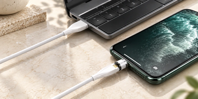
- What the Term Describes
- The Magnetic Mating Sequence
- Type-C and Magnetic Interface Locations
- Potential Mating Benefits
- Charging and Data Requirements
- Compatibility and Exposure Limits
- OEM Alternatives to a Device-Side USB-C Port
A Type-C magnetic connection combines USB-C with magnetic assistance for attachment and separation. It may use an adapter inserted into an existing USB-C port or a USB-C cable end paired with a custom magnetic pogo-pin device interface.
Charging, docking and supported data or signal functions depend on the complete connector, cable, assignments and device design.
What the Term Describes
'Type-C magnetic connector' generally refers to a wired system combining USB Type-C and magnetic mating. Attraction helps align and retain the parts, while touching conductive contacts carry power or signals.
USB Type-C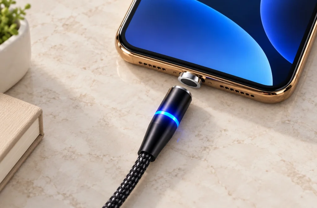
A consumer adapter usually leaves a small Type-C plug in the device. An OEM arrangement may instead place USB-C only at the source or cable end, with a custom magnetic contact interface on the device.
Identify the two interfaces separately. USB-IF defines Type-C plugs, receptacles, cables, orientation and connection requirements. Adding a proprietary magnetic interface does not make it a standardized USB-C magnetic format.
The Magnetic Mating Sequence
A detachable assembly typically has a USB-C tip seated in the device and a cable-side magnetic head. As they approach, attraction aligns the head with the tip; contacts in the interface then complete the circuit.
In this conductive-contact arrangement, magnets assist positioning, retention and release. Current and signals pass through metal pads or spring contacts selected for the design.
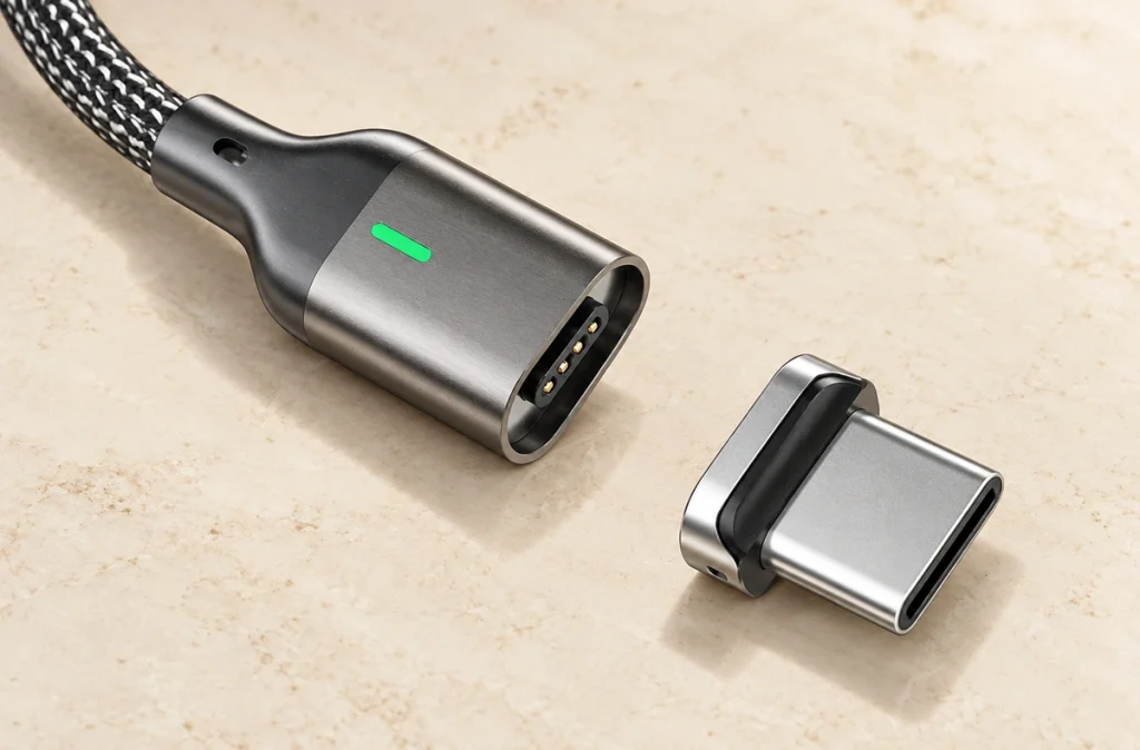
An OEM pogo-pin interface can avoid a conventional device-side USB-C receptacle. One physical path is:
USB-C power source → cable → magnetic connector → pogo pins / contact pads → device PCB.
Magnetic capture guides docking while spring contacts maintain pressure on the mating pads within their working stroke.
Type-C and Magnetic Interface Locations
Locate the USB-C connection and magnetic breakpoint before comparing products described by this term.
| Architecture | Device-Side Interface | Possible Application |
|---|---|---|
| Magnetic USB-C adapter | Existing USB-C receptacle with a removable magnetic tip | Phones, tablets or laptops |
| Magnetic USB-C cable | USB-C adapter or a matched magnetic interface | Consumer charging |
| USB-C to magnetic pogo-pin cable | Custom pogo-pin or pad interface | Wearables, medical electronics or OEM devices |
| USB-C-powered magnetic dock | Device contacts mated through the dock | Charging stations or portable products |
Scroll horizontally to view every column.
The detachable design adds a magnetic connection ahead of the original Type-C port while retaining the device's USB-C architecture.
An integrated magnetic interface belongs to the product design. Magtor magnetic cable connectors can use USB-A or USB-C at the cable end and configurable device-side contacts for charging, signals or ID functions.
Magnetic Cable ConnectorThe comparison of magnetic USB adapters and magnetic pogo cables explains these architectures further.
Magnetic USB Cable vs Magnetic Pogo Pin Cable: What’s the Difference?Potential Mating Benefits
A suitable magnetic interface can assist quick attachment, alignment, reduced repeated plug insertion and controlled release. Bring the head close so attraction and mechanical features guide the surfaces into contact.
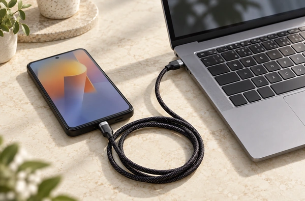
Leaving an adapter tip in the device can reduce insertion into its original receptacle. An integrated OEM interface may offer a low-profile connection, configurable contacts and easier frequent docking, subject to its design.
These options may suit watches, smart glasses, handheld equipment, portable medical products, docks and other compact electronics with repeated mating needs.
Charging and Data Requirements
Charging and data support require a suitable electrical design. Check the charger, cable, magnetic contacts, contact resistance, assignments, device electronics and supported charging or communication protocol; the USB-C shape alone establishes none of these.
Type-C provides reversible mating within a scalable connection system. USB PD and particular data rates still require their corresponding electrical implementation. USB-IF publishes separate connector, cable and Power Delivery specifications and compliance requirements.
USB Power DeliveryTwo contacts may be assigned to power and ground; additional paths can serve signals, detection, ID or custom functions. Higher-speed designs also need review of signal integrity, grounding, impedance, contact geometry and cable construction.
Compatibility and Exposure Limits
Magnetic USB-C accessories are not universally interchangeable. Tip geometry, layout, polarity, charging capability and data support may differ, even when both cables have USB-C ends.
Magnets can attract ferromagnetic particles. Dust, moisture, skin deposits and metallic debris may disrupt exposed contacts. Assess contact geometry, cleaning access, housing, plating and protection for the anticipated exposure.
Standard Type-C plugs, receptacles and cables have defined requirements, including separate standardized screw-locking configurations. A proprietary aftermarket magnetic breakaway adapter is not a universal USB-IF magnetic format and needs its own assessment.
standardized screw-locking configurationsOEM Alternatives to a Device-Side USB-C Port
A finished phone or laptop with USB-C may use a compatible magnetic adapter. During new-device development, assess whether a conventional USB-C receptacle is required on the device itself.
Frequent charging, blind docking, shallow installation, custom assignments or device-specific mechanical integration may justify a magnetic pogo-pin architecture:
magnetic pogo pin connectorUSB-C charger → USB-C cable end → magnetic pogo-pin connector → device contact interface.
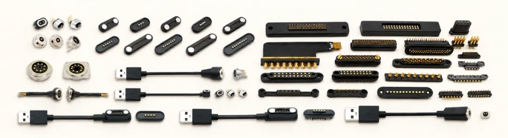
The source side can retain USB-C while the device uses a purpose-designed magnetic interface. Allocate power, ground, signals, detection and ID according to the circuit. Magtor can assess 2–16-contact assemblies with USB-A, USB-C, terminal, bare-wire or custom ends for OEM integration.
Use standardized USB-C when interoperability is a priority, and assess a custom interface for specialized docking, charging or mechanical/electrical needs. Define current, voltage, signals, count, device space, magnetic force, sealing, environment and mating cycles before deciding.
current, voltage, signal requirementsSelecting the Complete Connection Architecture
The term can describe either an adapter on an existing Type-C port or an OEM system with USB-C at the source and magnetic contacts at the device. Identify that architecture before assessing its capabilities.
Consumer adapters may make repeated attachment convenient. Compact OEM designs can instead use magnetic contacts for assisted alignment, frequent docking, configurable paths, small installation areas and custom power or signal circuits.
Define where the USB-C interface ends and the magnetic interface begins to select and validate the device's complete connection system.