
Magnetic USB Adapters and Integrated Pogo Cables: Choosing the Architecture
Published on September 23, 2026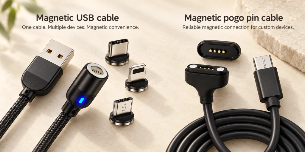
- Two Different Interface Architectures
- Detachable Magnetic USB Adapters
- Device-Integrated Magnetic Pogo Interfaces
- Comparing Integration and Functions
- Compatibility, Power and Data Conditions
- Compact-Device Applications
- Selecting an OEM Architecture
A detachable magnetic USB cable adds an adapter to a device's existing port. An OEM magnetic pogo-pin cable uses an interface designed into the device. Compare them by integration, compatibility, contact allocation, power and data functions, and customization needs.
Two Different Interface Architectures
Both use magnetic assistance, but the detachable USB design keeps a small USB-C, Micro-USB or similar tip in the existing receptacle. The cable then mates magnetically to that tip, leaving the device's original USB interface in use.
In an integrated design, magnetic capture and retention form part of the device interface. Touching pogo pins or pads carry power and any designed signal, detection or ID paths. Magtor magnetic cable connectors can combine project-specific contact counts with USB-A, USB-C, terminal or bare-wire ends.
Magnetic Cable Connector range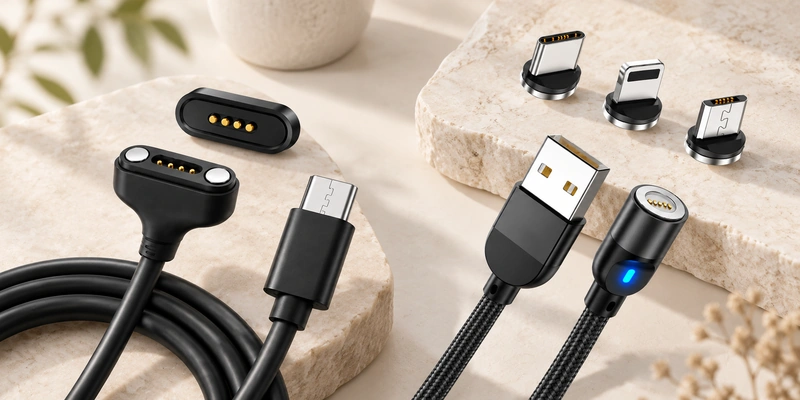
The distinction is architectural. A detachable USB adapter may itself contain spring contacts; compare an accessory added to a standardized device port with an interface engineered directly into the product.
Detachable Magnetic USB Adapters
The assembly usually contains a cable, magnetic head and removable tip. The tip fits the existing USB-C, Micro-USB or other receptacle and may stay there. Bringing the head close aligns its contacts with the tip, avoiding repeated insertion of the original plug.
Its physical power path can be represented as:
Power source → cable → magnetic interface → detachable USB tip → device USB port.
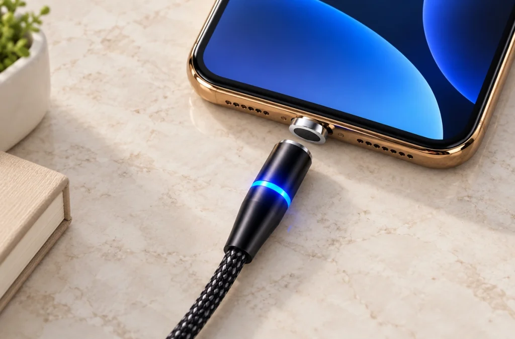
This approach can change daily cable attachment without redesigning a device that already has USB. Assess the proprietary magnetic breakpoint separately from the standardized USB interface. USB-IF specifies the Type-C plug, receptacle and cable system, including reversible mating and supported power/performance implementations; adding a magnetic adapter does not establish conformity.
USB-IFUSB Type-C Cable and Connector Specification — USB-IFDevice-Integrated Magnetic Pogo Interfaces
Develop the magnetic cable with its device-side counterpart. Magnets position the halves and spring contacts compress against mating surfaces to complete the electrical path. The opposite end may use USB-A, USB-C, bare wire, terminals or another connector according to the architecture.
One example of this path is:
USB / power source → cable → magnetic pogo-pin head → device contact pads → PCB.
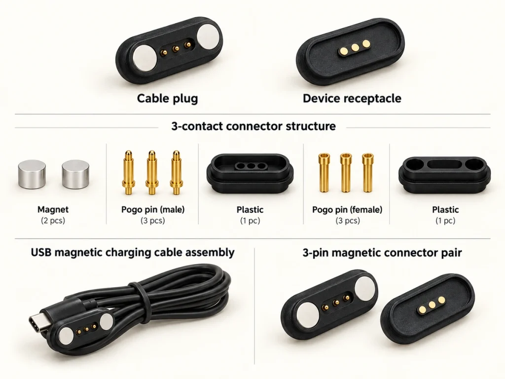
The device functions can determine the contact count independently of a standard USB layout. Two contacts may suit a simple power path; 4-, 5-, 6- and 8-pin configurations can allocate additional paths to signals, detection, ID, control or custom functions. The count does not specify the pinout.
2 Pin Magnetic Charging Cable4 Pin Magnetic Charging Cable5 Pin Magnetic Charging Cable6 Pin Magnetic Charging Cable8 Pin Magnetic Cable ConnectorComparing Integration and Functions
A detachable adapter adds a magnetic connection ahead of an existing USB port. An integrated cable interface is developed as part of the device's charging or other electrical connection.
| Comparison Feature | Detachable Magnetic USB Cable | Device-Integrated Magnetic Pogo Cable |
|---|---|---|
| Device interface | Existing USB-C, Micro-USB or similar receptacle | Project-specific contact interface |
| Magnetic breakpoint | Cable head to removable USB tip | Cable head to device-side counterpart |
| Device changes | Often no new device interface is needed | Included in product development |
| Contact allocation | Determined by adapter design | Defined for the project |
| Compatibility | Matched adapter, cable and supported USB functions | Matched mechanical and electrical specifications |
| Power capability | Depends on cable, contacts and USB implementation | Specified for the contact system and device |
| Data or other signals | Depends on adapter wiring and protocol support | Can allocate power, signal, ID or control paths |
| Cable end options | Primarily USB-oriented | USB-A, USB-C, bare wire, terminals or custom ends |
| Magnetic polarity | Set by the accessory design | Specified during interface development |
| Housing integration | Uses the device's existing USB opening | Can be incorporated into the enclosure |
| Typical market | Consumer accessory or retrofit | OEM product integration |
| Application examples | Phones, tablets and existing USB devices | Wearables, smart glasses, medical electronics and docks |
Scroll horizontally to view every column.
Magnetic capture and extra contacts do not establish speed or data support. Review current rating, contact resistance, wire gauge, cable length, contact allocation and the electronics on both sides. Magtor specifications are assessed per structure, so equal pin counts need not mean electrically identical cables.
Compatibility, Power and Data Conditions
A detachable design still needs a compatible USB receptacle and a matched proprietary tip and cable. For an integrated interface, dimensions, pitch, pin assignments, electrical polarity, magnetic polarity, compression, mating direction, voltage and current must match. The same contact count does not establish compatibility.
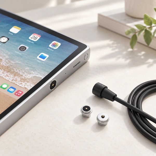
Neither architecture has a universal current rating. Capability depends on contact design, resistance, conductor size, cable construction, thermal conditions and the charging circuit. A USB-C source-side plug does not by itself provide USB PD or a particular power level; the full implementation determines available functions.
An OEM interface can allocate contacts from its schematic. Four might serve power, ground and two signals; five, six or eight may add ID, detection, control or further signals. These examples need the cable, PCB and electronics designed together, rather than being universal pin maps.
Compact-Device Applications
A detachable adapter can require less interface development when the product already has USB and its housing and PCB will stay unchanged. This makes it a possible consumer-accessory or retrofit approach, subject to checking the complete assembly.
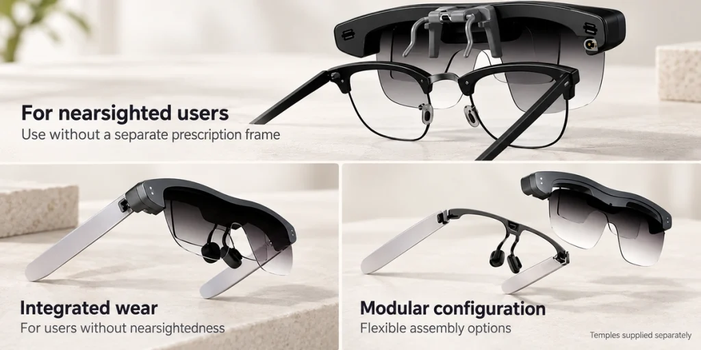
Integrated magnetic interfaces are an option while designing wearables, smart glasses, medical electronics, beauty products and docks. Requirements may include a small contact area, magnetic capture, frequent mating, a particular cable exit and detection or signal paths. Two contacts can be a starting point for simple charging; four or more should follow the schematic.
2 Pin Magnetic Charging CableFive-, six- or eight-contact cables offer more paths to allocate among power, signals, ID, detection and control. Select the final count from the device's required electrical functions.
5 Pin Magnetic Charging Cable6 Pin Magnetic Charging Cable8 Pin Magnetic Cable ConnectorSelecting an OEM Architecture
Start with the device architecture. An existing USB product that only needs easier daily attachment may use a detachable adapter with less modification. A new interface, smaller custom area, magnetic capture, specific mating direction, dedicated signals or enclosure integration may justify an OEM magnetic pogo-pin design.
Before approving samples, define count, contact functions, voltage and current, pitch, device-side dimensions, electrical and magnetic polarity, working compression, cable length, gauge, exit direction and end type. Magtor magnetic cable connectors include USB-A, USB-C, bare-wire and terminal options assessed with the actual PCB and enclosure.
Magnetic Cable Connector solutionsA detachable USB adapter modifies attachment to an existing port; an integrated magnetic cable belongs to the device-interface design. Decide that architecture before finalizing dimensions, pin assignments and electrical validation.