
Magnetic Pogo-Pin Connectors: How the Interface Works
Published on August 19, 2026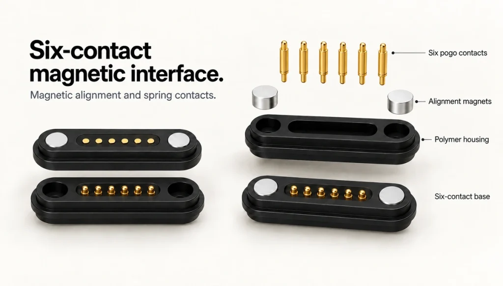
- Defining the magnetic spring-contact interface
- The mating and conduction sequence
- Components and their roles
- Possible design benefits and limitations
- Application requirements
- Eight selection checks
- Frequently asked questions
A magnetic pogo-pin interface combines spring-loaded conductive contacts with magnetic guidance and retention. It can provide a dedicated connection for power, charging, signals or data where the circuit supports those functions. Wearables, medical products, industrial devices and other electronics may use this compact docking approach, subject to their specific requirements.
Defining the magnetic spring-contact interface
In this assembly, magnets help position and retain the mating halves. Spring-loaded contacts press against corresponding conductive surfaces to form the electrical connection.
magnetic spring-contact interface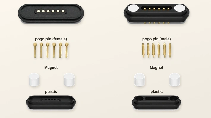
A typical pair has spring contacts on one half and matching pads or contacts on the other. Magnetic guidance brings the halves toward the designed position; the housing sets final alignment and the pins compress within their working travel to establish continuity.
spring-loaded conductive contactsThe two functions are:
Magnetic guidance and retention of the joint.
Conductive contact for assigned power or signals.
Spring pressure maintains contact without depending solely on the insertion action of a conventional plug. This can suit repeated docking, a compact envelope, controlled removal or difficult-to-see mating, where the contact travel and geometry are properly designed.
Select the contact count from the required circuit paths. A two-contact example may provide supply and return; additional contacts can serve data, sensing, identification or control where the device implements them.
A six-contact assembly offers six available contact positions for the device’s electrical allocation. Internal connections and parallel paths may reduce the number of independent circuits; there is no universal six-contact pinout.
six-contact magnetic assemblyThe mating and conduction sequence
Magnetic attraction, spring compression and metal-to-metal contact perform separate roles in the connection.
Within the designed capture range, attraction assists placement of the mating halves. The housing and polarity arrangement control the intended final position; guidance does not compensate for every possible offset or orientation.
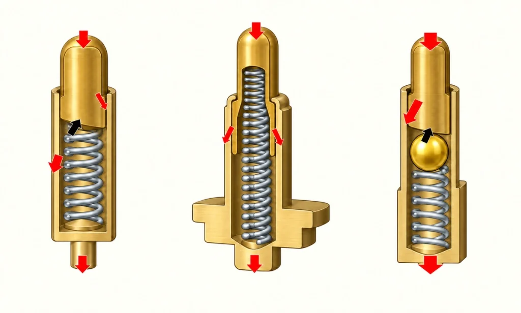
When engaged, a pin’s plunger presses against its matching surface and compresses the internal spring. That compliance accommodates limited axial variation within the specified working range. Lateral alignment and retention remain mechanical design requirements.
A typical sequence is:
Approach → Magnetic guidance → Spring-contact compression → Conductive engagement → Assigned power or signals
The joint releases when an appropriate separating force overcomes its retention. Assess pull direction, cable loading and device support rather than assuming every accidental pull is harmless.
Magnetic guidance can assist mating when the interface is difficult to see and may reduce some positioning hardware. It does not remove the need for housing alignment, stops, retention and electrical fault assessment.
Possible function allocations include:
Two contacts may provide a positive supply and return.
Added contacts may provide detection or control paths.
Four- or five-contact layouts may combine supply paths and communication where designed for the intended interface.
Six or more contacts provide further allocation options for power, returns, data, identification, sensing or auxiliary functions.
Approve the actual contact map, polarity, allowable current, engagement sequence and protection with the device circuit. Matching pin count does not establish compatibility.
The power-and-signal wiring guide explains how to document the allocation and check the connection before energizing.
power-and-signal wiring guideComponents and their roles
A typical assembly includes spring contacts, matching conductive surfaces, magnets, an insulating housing and board or cable terminations.
| Component | Role in the assembly |
|---|---|
| Pogo Pin | Provides a compliant conductive contact |
| Contact Pad | Forms the matching conductive surface |
| Magnet | Assists alignment and retains the joint |
| Housing | Controls position and supports the contact structure |
| Plating | Provides the specified contact finish for electrical and environmental requirements |
| PCB / Cable Termination | Connects the interface to the device or cable circuit |
Scroll horizontally to view every column.
A basic pogo pin has a plunger, barrel and spring. Pressing the plunger compresses the spring and produces contact force. The current path depends on the particular internal construction, rather than always passing solely through the spring.
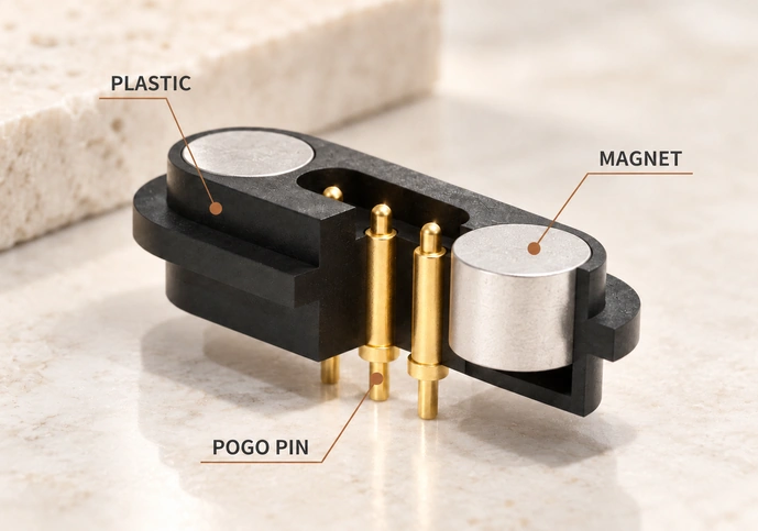
Suitable conductive alloys may use a gold finish over an underlying layer. Select material, finish thickness, force, working height and contact geometry from the load, exposure, mating-life target and cost requirements. Confirm the actual model specification.
Magnet size, position, polarity and attraction affect capture, final alignment and removal effort. Review them with the spring reaction, housing and mechanical stops.
For water, sweat, dust or outdoor exposure, a magnetic interface can form part of a sealed structure. Verify the assembled enclosure, contact protection and chemical conditions; selecting a sealed connector concept does not itself establish the finished device’s protection.
sealed magnetic connector rangePossible design benefits and limitations
Guided placement, quick attachment, compact packaging and a dedicated contact layout can be useful for repeated docking. Their value depends on the complete application and validation.
Guided placement: Magnets assist positioning within the designed capture range, reducing manual alignment effort while the housing sets the final contact location.
Attachment and removal: The joint avoids a conventional deep plug-insertion action. Contact compression, retention and separation still involve forces to specify.
Repeated docking: Spring-contact assemblies can be selected for a defined mating duty. Confirm life under the actual compression, finish, contamination and load conditions.
Electrical allocation: Assign supply, return, data, detection, sensing or other functions from the product’s circuit, including the required signal levels and protocols.
Compact packaging: A dedicated geometry can be evaluated against the available PCB and enclosure space, rather than assuming every standard receptacle will fit.
printed circuit boardSealing options: Surface mating can be incorporated into a sealed enclosure without a deep open socket where the complete housing, cable exit and contact protection are designed and tested.
Handling: Guided placement may help one-handed charging, repeated docking or a connection that is difficult to see. Assess the actual usability and retention rather than assuming universal ease of use.
A standard interface such as USB-C may be preferable where standardized mating, protocol support and compatible accessories are priorities. Actual data and charging functions still depend on the device and cable implementation.
USB-C interfaceThe magnetic and standard pogo-pin comparison discusses the different alignment and retention arrangements in more detail.
magnetic and standard pogo-pin mechanisms comparedApplication requirements
Consider this mechanism where repeated charging, docking, a compact mating area, controlled release or combined power and signals address the product requirements.
Possible application categories include:
Wearable electronics
Charging cradles
Medical and healthcare equipment
Portable electronic products
Connected home products
Industrial devices
Sensor products
Handheld equipment
Robotic systems
Test fixtures and docking equipment

Each application brings a different set of electrical, mechanical and environmental constraints.
A wearable may emphasize size and weight. A medical product may need repeated docking, suitable materials, cleaning compatibility and device-specific validation. An outdoor sensor may need enclosure sealing, while industrial equipment may prioritize load capacity, retention, vibration and mechanical support.
Function count also matters. A five-contact pair can provide additional paths for signals, sensing or control beyond a two-contact supply layout, where the circuit and contact specifications support them.
five-contact magnetic assemblyA higher-current assembly needs suitable conductive paths, resistance control, cable size, thermal behaviour and retention. Magtor treats high-current magnetic designs separately from small general-purpose assemblies; their ratings cannot be transferred between configurations.
dedicated high-current magnetic designsEight selection checks
Begin with supply and signal requirements, contact count, available space, retention, environment and the intended service life. Use those inputs to evaluate a representative mating assembly.
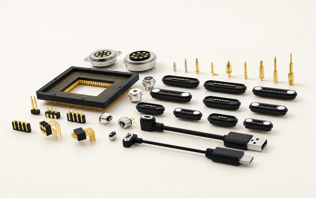
Review these eight specification areas:
1. Contact count and allocation
Identify every independent circuit path, including the required returns.
A power-only layout may need supply and return. Data, identification, sensing, charging control or auxiliary functions can require more contacts with explicitly defined levels and protocols.
Verify the actual pinout even when two assemblies have the same contact count.
2. Allowable voltage and current
Size and validate contacts, conductors, PCB traces and the full circuit for the load. At higher current, resistance, conductor size, temperature rise and stable engagement all need particular attention.
3. Initial and aged contact resistance
Define acceptable resistance for the charging or supply path. Check not only the initial value but its change after the specified mating duty, wear, contamination and environmental tests.
4. Installed height and working travel
Keep each engaged contact in its permitted compression range at all tolerances. Too little compression may cause intermittent contact; excessive compression can add stress and reduce useful life.
5. Retention and orientation
Specify enough retention for engagement and spring reaction while keeping intended removal manageable. The strongest magnet is not necessarily the appropriate choice.
Magnet polarity and mechanical keying can reduce incorrect mating. Validate partial and unintended orientations rather than assuming those measures eliminate all errors.
6. Envelope and mounting
Review board position, enclosure wall thickness, connector footprint, cable exit and the interface with the external housing.
A dedicated assembly may help where the available envelope cannot accommodate a suitable standard part.
7. Ingress and chemical exposure
For rain, sweat, dust, cleaning fluids or outdoor use, assess the full enclosure and the separate chemical-exposure requirements.
Protection depends on the housing, seals, adhesive or overmolding, mounting interface, exposed contacts and device integration. Magtor’s sealed magnetic connector range provides a starting point for a design review; confirm the required assembled-device tests.
8. Mating life and mechanical duty
Set the reliability target from connection cycles, finish wear, spring fatigue, contamination, cable loads, shock and vibration. The chosen configuration needs validation for that duty.
Balance electrical performance, fit, guidance, protection, handling and manufacturability. Contact count or magnet strength alone cannot identify the most suitable assembly.
Magtor can review a dedicated magnetic contact pair around the required allocation, envelope, retention and device-integration conditions.
MagtorIn summary, a magnetic spring-contact pair uses magnets for positioning and retention and conductive contacts for the assigned charging, supply or signal functions. It offers a detachable layout that can be tailored for repeated connection, with actual performance determined by the complete design.
Frequently asked questions
Can the assembly be designed for water exposure?
It can form part of a sealed device using appropriate housing seals, O-rings, adhesive or overmolding and a suitable contact finish. Validate the complete connector and enclosure for the specified ingress and corrosion conditions; spring pins alone do not establish waterproof performance.
What determines its useful mating life?
Pin design, spring force, finish, compression, contamination and mating conditions all affect life. Thousands or tens of thousands of cycles are possible design targets for suitable configurations, not a guarantee for every model. Confirm the required duty through application-specific life testing.
Can the same assembly carry power and data?
A multi-contact pair can allocate separate supply, return, data, sensing, identification or control paths. Four-, five- or six-contact examples can combine charging and communication only where the pinout, signals and electrical limits are designed and validated for the device.
How can contact performance be maintained?
Keep mating surfaces free of the dust, oil, moisture or oxidation relevant to the application, using approved cleaning methods with power disconnected. Suitable finish, working height, compression and alignment support stable resistance; worn or damaged parts may require replacement.
Which features can be tailored for a device?
A custom review can cover contact count, pitch, current target, working height, retention, polarity, dimensions, mounting, cable exit, finish and sealing. This is useful where a suitable standard part does not fit the board or enclosure, with feasibility and validation agreed for the actual configuration.