
How Smart Mugs Charge: Designing the Cup-to-Base Interface
Published on August 10, 2026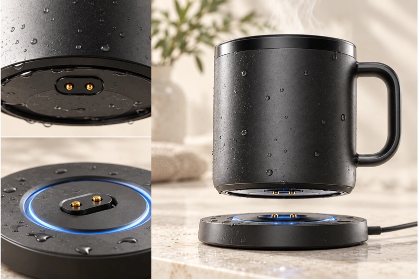
- Smart-mug electronics and heating
- The charging power path
- Three charging approaches
- Contact charging and induction compared
- Liquid exposure and sealing
- When two contacts are sufficient
- Circular interfaces and orientation
- Why use compliant spring contacts?
- Six connector design checks
- Sealed interfaces and ordinary charging pads
- Using USB-C with a magnetic base
- Selecting a charging interface
- Smart-mug design support from Magtor
- Choosing the charging architecture
A rechargeable smart mug uses a heater and controls to maintain its selected beverage temperature. A dedicated base can deliver charging power through fixed contacts, spring contacts, a magnetic interface or induction. This guide explores those arrangements and the sealing considerations around a frequently handled cup.
magnetic interfacesSmart-mug electronics and heating
A smart mug is an electronically controlled cup that maintains coffee, tea or another drink within a selected temperature range. The actual range depends on the product.

Depending on the design, its components can include:
Heating elements
Rechargeable battery
Temperature sensors
Battery management circuitry
Microcontroller
Bluetooth connectivity
Mobile app control
LED indicators
Charging contacts
Insulation slows heat loss; an electronic heater uses electrical energy to maintain temperature. A product can use both, but active heating creates a power and charging requirement.
Plan the charging interface as part of that complete electrical and mechanical system.
The charging power path
A battery-powered mug carries its rechargeable battery in the body. Away from the charger, that battery supplies the heater and control electronics.
For recharging, the user places the mug on its matching base or coaster.
A typical path is:
Power supply → charging base → mating contacts → battery-management and charging circuit → battery

USB-C or another suitable connector can supply the base. The separate mug-to-base interface can be designed for frequent lifting and replacement, with its own contact geometry and controls.
The external input and docking interface serve different roles.
A common USB input can feed the base while a compact spring-contact or magnetic interface connects the cup. Their requirements should be assessed at their respective locations.
Three charging approaches
Choose the architecture from the charging load, enclosure, ingress requirement, cost, handling routine and available space. No single method meets every smart-mug requirement.
1. A fixed-contact charging base
One option uses metal contact surfaces on a charging coaster.
At the correct position, contacts on the mug base touch corresponding conductors on the charger to establish the power path.
This can offer a simple conductive arrangement. Automatic charging still requires correct engagement and the intended detection, protection and power-control behaviour.
The mug underside can encounter water, coffee, condensation and cleaning deposits. Evaluate those exposures rather than judging a clean new contact alone.
Select contact materials and finishes together with mechanical seals and corrosion requirements.
2. A magnetic spring-contact base
A magnetic connector is another possible docking interface.
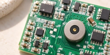
Permanent magnets assist placement and retention. Spring-loaded contacts conduct electricity when correctly aligned and compressed, with a suitable clean mating surface.
The intended docking sequence is:
Mug approaches the base → guided alignment → contacts compress → charging control permits power
For a cup lifted and replaced throughout the day, guided docking can reduce handling effort. Confirm that the actual placement and retention arrangement delivers that experience.
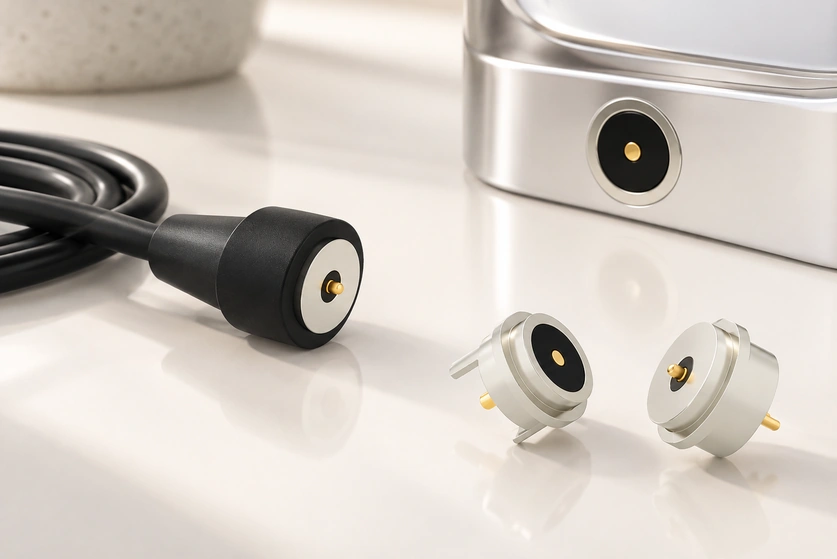
A custom magnetic assembly can fit the mug’s underside, subject to the contact layout, return path and sealing constraints.
3. Inductive charging
An inductive system transfers charging energy without direct mating power contacts.
Coils in the cup and its base couple energy electromagnetically, with the associated control electronics. Compatibility depends on the actual system; induction does not imply Qi certification.
Removing exposed power contacts can simplify the exterior surface. The complete enclosure still needs its own sealing assessment.
Induction requires suitable coils, electronics and positioning. Compare efficiency, heat, charging speed, thickness and cost using actual designs rather than assuming a universal advantage.
Make the decision at system level: efficiency, ingress protection, cost, packaging and the user’s docking routine all matter.
Contact charging and induction compared
Both approaches can charge a smart mug, using different transfer mechanisms.
| Design Factor | Magnetic Pogo Pin Charging | Wireless Charging |
|---|---|---|
| Electrical contact | Physical contacts | No direct mating power contacts |
| Alignment | Magnetic guidance plus contact geometry | Coil positioning required |
| Power efficiency | Low-loss conduction is possible; assess the complete design | Depends on system design |
| Structure | Conductive path plus the necessary charging controls | Coils and associated transfer electronics |
| Customization | Contact and housing geometry can be customised | Coil and circuit dependent |
| Waterproof design | Requires seals at contact and enclosure interfaces | Can avoid contact penetrations; the full enclosure still needs seals |
| Charging base integration | Possible with guided and protected contacts | Possible with suitable coil position and controls |
| Manufacturing cost | Depends on contacts, seals, tooling and volume | Depends on coils, electronics, structure and volume |
| Maintenance | Contacts require protection | No exposed power contacts |
Scroll horizontally to view every column.
Neither method is the universal choice.
Compare each against the product specification.
Magnetic spring contacts are worth considering where conductive transfer, custom packaging and repeated docking are priorities. Verify the required efficiency, sealing and life instead of inferring them from the mechanism.
Liquid exposure and sealing
A cup’s charging area may encounter liquids and residues during use and cleaning.
Relevant exposures can include:
Water
Coffee
Tea
Milk
Sugar residue
Steam
Condensation
Cleaning water
Detergent residue
These liquid and residue conditions need a specific assessment rather than a generic dry-electronics assumption.
A clean laboratory connection can behave differently after repeated wetting or residue build-up. Include representative exposure and maintenance conditions in the validation plan.
Contact stability
Water or beverage deposits can contaminate the mating surfaces and change their resistance.
Unstable resistance can produce excessive voltage drop, interrupted charging or unwanted heating. Check the installed interface under the specified load.
Corrosion and long-term contact behaviour
Under moisture exposure, an unsuitable metal or plating system may oxidise or corrode. Select the finish for the actual liquid and cleaning conditions.
Review initial conductivity together with wear and environmental resistance; the new part’s electrical result is only the starting point.
Water paths into the product
Protect the battery, PCB and heater-control area from water entry, while separately maintaining safe and reliable exposed contacts.
The contact assembly must be integrated with the enclosure seals.
Where liquid exposure is expected, a sealed magnetic interface can help form the charging connection. The complete cup, installation and exposure still require validation.
sealed magnetic interfaceWhen two contacts are sufficient
Two contacts may provide a straightforward interface when only charging power crosses the external connection. The device must still provide suitable charge control, polarity and protection.
two-contact magnetic connectorA possible allocation is:
| Pin | Example function; verify the actual mating drawing |
|---|---|
| Pin 1 | VCC / Positive |
| Pin 2 | GND / Negative |
Scroll horizontally to view every column.
This example assigns the interface solely to power and its return.
Simple Electrical Architecture
If data and control remain inside the mug or use a wireless link, the external charger may not need separate signal contacts. Confirm that against the actual architecture.
Keep the contact count matched to the required functions.
Compact Connector Structure
Fewer contacts can leave more layout options for a small circular or custom assembly. Compare the actual footprint and spacing.
Check the available underside envelope rather than assuming a particular connector diameter fits.
Easier Mechanical Integration
For a two-contact interface, arrange magnets, springs, seals and PCB connections together. The smaller function count offers options but does not remove their mechanical constraints.
Suitable for Frequent Docking
A working day can involve repeatedly lifting the cup and replacing it on its charger.
A guided contact base can avoid inserting a small plug on each return.
Correct placement and power control must still confirm that charging can begin.
Circular interfaces and orientation
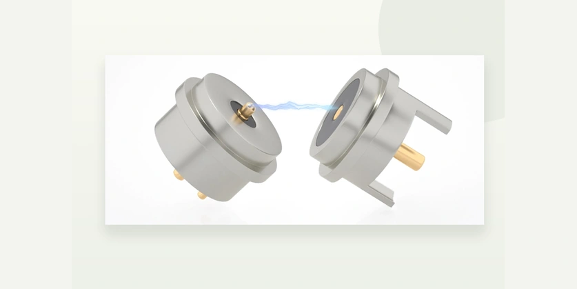
Rotational alignment influences the charging routine.
If the contacts require one angular position, the user may have to turn the cup until the mating layout aligns.
Repeatedly finding that angle can add an unnecessary handling step.
A circular layout can be designed to reduce the placement burden.
The electrical arrangement, magnet polarity and contact geometry determine whether multiple angular positions are permitted. A round housing alone does not establish 360-degree operation.
A useful interaction target is:
Pick up the mug → drink → place it back on the charger
Design for straightforward replacement on the base, while preserving correct electrical engagement. Do not claim that every circular connector works at every angle.
Similar docking considerations can arise in smart mugs, kettles, personal-care products, wearables and other docked electronics. They do not establish a small contact assembly’s suitability for a kettle’s high-power heater circuit.
Why use compliant spring contacts?
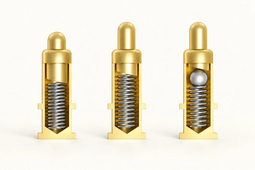
A pogo pin provides a conductive contact with spring travel.
When the cup seats on the base, the contact compresses within its intended working range and applies pressure to the mating surface.
Within that range, compliance can accommodate small variations in:
Housing dimensions
Charging base position
Mug bottom flatness
Assembly tolerances
Long-term mechanical wear
A rigid contact depends on positioning or compliance elsewhere in the assembly. Compare the complete mechanical arrangement.
A spring contact tolerates limited axial variation while maintaining pressure, provided the working-height and force limits are respected.
This can improve repeatability during docking when the assembled tolerances and alignment are controlled.
Six connector design checks
Start with the full electrical and mechanical specification. The visible connector shape alone does not establish a suitable charging interface.
Charging Current and Voltage
Set the maximum charging current and working voltage from the battery system and its protection requirements.
For the current path, also review:
Contact resistance
Voltage drop
Current density
Temperature rise
- Pin diameter
Number of power contacts
Apply the selected current limit under the actual ambient, cooling, wiring and enclosure conditions, rather than relying on a nominal number alone.
Contact Resistance
Low contact resistance helps limit resistive loss and voltage drop.
Track resistance after repeated docking and the relevant exposure tests as well as on a new interface.
Define an initial value and acceptable change after the agreed lifecycle tests.
Waterproof Requirement
Base the sealing requirement on the complete cup’s use and permitted cleaning method. An IP label does not establish dishwasher or detergent compatibility.
The application may require splash protection, temporary immersion or another stated exposure. Specify the actual conditions without assigning a default grade.
The finished cup’s ingress protection depends on enclosure geometry, seals, assembly controls and mating state. A connector rating alone is insufficient.
Magnetic Force
Retention must hold the contacts at the required working position.
Too much attraction can make lifting the mug awkward or stress the base.
Set both retention and release requirements:
Stable electrical engagement with manageable cup removal
Evaluate cup weight, interface location, lifting direction, magnet layout and spring reaction together. Attraction and measured release force are not interchangeable.
Contact Plating
Specify the contact finish for repeated use around moisture and residues.
Assess:
Corrosion resistance
Wear resistance
Contact resistance
Mating cycles
Environmental exposure
Gold or another engineered finish may be appropriate. Specify the materials, layers and thickness against performance and cost requirements rather than selecting by colour.
Mating Cycle Life
Count all expected returns to the base in the daily use pattern.
Repeated use over several years can accumulate substantial cycles; calculate the target rather than inventing a universal count.
Include checks for:
Pogo pin spring fatigue
Spring-contactPlating wear
Magnet stability
Contact contamination
Resistance changes
Mechanical deformation
Reproduce the relevant docking, load and exposure conditions in lifecycle validation. A handful of ideal connections does not demonstrate long-term reliability.
Sealed interfaces and ordinary charging pads
Exposed pads may suit a particular dry indoor application if its requirements permit them.
A smart-mug interface can additionally face regular beverage residue and moisture, so assess the finish, cleaning and seal arrangement for that exposure.
A sealed magnetic assembly offers possible design features:
Guided alignment: Magnets and mechanical features assist correct docking.
Compact layout: Housing geometry can be developed around the cup.
Repeated docking: Charging need not involve conventional plug insertion on every return.
Enclosure integration: The device-side interface can form part of an appropriately designed and validated seal.
Contact layout: Contact count, pitch, magnet position and housing shape can be tailored to the application.
Assess waterproofing at complete-product level. The connector is one element of the cup’s sealing structure and does not establish the result alone.
Using USB-C with a magnetic base
Using USB-C with a magnetic baseUSB-C can provide a common external supply connection without placing the receptacle directly on the mug. Confirm the power source, cable and implemented charging functions.
USB-COne combined arrangement is:
USB-C Adapter → Charging Base → Magnetic Connector → Smart Mug
A compatible USB-C input supplies the charging base.
The cup receives controlled charging power through the magnetic contact interface.
Each interface addresses a different part of the charging system.
USB-C provides the external connection while magnetic contacts can simplify daily mug-to-base docking. The complete power path still needs the intended controls and protection.
A USB-C port on the cup involves repeated cable insertion and an enclosure opening to seal against the permitted exposure. A properly sealed port is possible; the packaging and handling requirements determine its suitability.
For frequent lifting and replacement, a guided contact base may offer a more convenient routine. Check that in the actual product design.
Selecting a charging interface
Define the application requirements before choosing a connector model.
Provide the supplier with:
Input voltage; charging current; installation space; contact count and functions; connector diameter; ingress target; mounting; retention and release forces; mating-cycle target
These inputs support a comparison between an existing part and a custom interface. Confirm fit and performance against the proposed design.
Two contacts may cover a charging-only path, with the required polarity and protection.
Identification, communication, temperature monitoring or accessory detection may call for additional contacts, depending on the circuit and any shared functions.
Define the electrical functions before choosing how many contacts to use.
Smart-mug design support from Magtor
The charging mechanism must fit the mug’s electrical and mechanical requirements. Where a standard part does not fit, review the contact assembly with the enclosure instead of forcing the product around an unsuitable component.
Magtor develops magnetic spring-contact designs for compact charging and power interfaces, including smart mugs and other consumer products. Assess the specific project’s packaging and validation requirements.
MagtorFor charging power alone, a two-contact Magtor layout can use VCC and GND with magnetic guidance and spring contacts. Confirm its polarity, working height and electrical limits for the battery system.
A sealed Magtor design can be developed around the cup’s geometry where water, coffee, humidity or cleaning are relevant. State those exposures explicitly; a water-ingress target does not prove chemical, dishwasher or food-contact compliance.
Custom design inputs include:
Connector dimensions
2-pin contact layout
Pogo pin diameter
Pin pitch
Rated current
Magnetic force
Magnetic polarity
Contact plating
Housing structure
Waterproof sealing design
PCB mounting
Cable assembly
Charging base interface
Develop the interface around the mug’s electrical functions, enclosure and docking arrangement rather than treating the connector as an isolated component.
For an OEM or ODM design, review the magnetic interface early in mechanical development, before the base and cup geometry become fixed.
That allows magnet and contact locations, PCB arrangement, seal area, dock shape and user handling to be coordinated in the same review.
Choosing the charging architecture
Choose from the product requirements rather than a universal technology ranking.
Induction is worth considering where avoiding exposed power contacts is a priority. The enclosure and transfer system still need validation.
Direct USB-C can suit a product where the common plug interface and accessory requirements outweigh the convenience of a drop-on base.
Magnetic spring contacts can suit conductive charging, frequent docking, compact packaging and custom guided engagement. Check the required efficiency, seals and reliability in the proposed assembly.
One architecture to evaluate is:
USB-C input → charging coaster → sealed two-contact interface → battery-management and charging circuit → mug battery
This separates the external supply connector from the cup-specific docking mechanism.
Conclusion
A rechargeable smart mug can use a dedicated base to deliver controlled battery charging through fixed contacts, spring contacts, a magnetic connector or induction. The actual mechanism depends on the product.
Plan for repeated docking, liquid and coffee exposure, cleaning, corrosion and mechanical wear as well as supplying electricity.
When only power crosses the interface, two contacts can provide VCC and return. Magnetic guidance can simplify docking, with geometry, polarity and working compression defined for the actual base.
For liquid exposure, a sealed magnetic assembly can support the enclosure design. Long-term contact performance and ingress protection still need application-specific validation.
Define voltage, current, space, ingress conditions, magnetic-force targets, mounting and life requirements early. Those inputs support selection or customisation of an interface suited to both the charging circuit and everyday handling.
Frequently asked questions
How does a rechargeable smart mug receive power?
A rechargeable smart mug may use a dedicated coaster or base. The charger supplies the battery-management circuit through fixed metal contacts, spring contacts, a magnetic assembly or an inductive system, depending on the design.
Can a smart mug charge inductively?
Some designs use induction; others use conductive contacts. Compare efficiency, sealing, cost, packaging and the product’s intended charging routine before choosing.
What can a magnetic interface offer?
Magnetic guidance can reduce manual plug insertion and assist repeated docking. The housing, contact geometry and seals can be tailored to the cup, with alignment and retention validated for the intended use.
When are two contacts sufficient?
Yes, where the external connection needs only positive power and its return. Charge control and protection remain necessary. Extra signals, identification or communication can require further contacts according to the architecture.
Can the magnetic interface form a waterproof seal?
They can be designed as part of a waterproof product. The final result depends on contacts, housing interfaces, seals, mounting and assembly quality, tested together under the stated ingress conditions.
How should I select the base interface?
There is no universal option. A sealed two-contact magnetic interface may suit compact charging-only designs with repeated docking and moisture exposure. Select it against voltage, current, space, sealing, retention and release, and lifecycle requirements.