
Charging Docks and Magnetic Cables: Choosing for the Device's Use
Published on September 21, 2026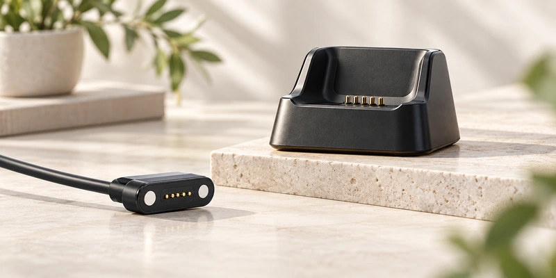
- Dock and Magnetic-Cable Architectures
- Comparing the Two Forms
- When a Fixed Dock Fits
- When a Portable Magnetic Cable Fits
- Mechanical Design Requirements
- Sealing and Wearable Exposure
- Functions Beyond Charging
- Choosing for Daily Use
A dock positions a device on a fixed charging platform; a magnetic cable offers a portable connection with flexible routing. Either may use magnetic alignment and pogo-pin contacts. Choose by positioning, portability, cable motion, enclosure, sealing and the product's charging routine.
pogo pinsDock and Magnetic-Cable Architectures
A dock combines conductive contacts with physical support. Guides, magnets or housing geometry can align the device when it is placed on or into the base.
charging dockA magnetic cable carries the mating head at its end. Bringing the head to the device lets magnetic force assist alignment and retention at the interface.
magnetic charging cablemagnetic connector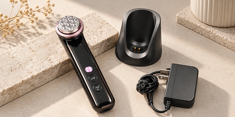
For conductive-contact versions, the electrical path may be similar:
Power source → cable → pogo-pin contacts → device contact pads → charging circuit.
The choice chiefly concerns how the mechanical interface is arranged around the device; the power-transfer principle need not differ.
Comparing the Two Forms
| Design Factor | Charging Dock | Magnetic Charging Cable |
|---|---|---|
| Device positioning | Defined by the dock geometry | More flexible; mating position still needs control |
| Portability | Often less convenient to carry | Often easier to carry |
| Desktop use | Can suit a fixed station | Can suit a desktop connection |
| Alignment | Mechanical guides and/or magnetic capture | Head geometry and magnetic capture |
| Cable motion at the contact | Typically reduced by the dock structure | More movement may reach the head |
| Use during charging | May be constrained by the dock position | Can offer more freedom where device use is permitted |
| Breakaway behavior | Depends on dock requirements | May be useful for portable products |
| Mechanical integration | Dock and device interface | Cable head and device interface |
| Typical setting | Desk, bedside station or cradle | Travel, portable charging or mobile use |
Scroll horizontally to view every column.
Select according to normal charging use. Neither physical form automatically suits every device better.
When a Fixed Dock Fits
Consider a dock when the device usually returns to the same charging location.
Possible applications include handheld scanners, medical devices, beauty devices, POS terminals, charging cradles and wearable accessories. Placing the device on the base lets its mechanical features control position instead of requiring a separate cable connection each time.
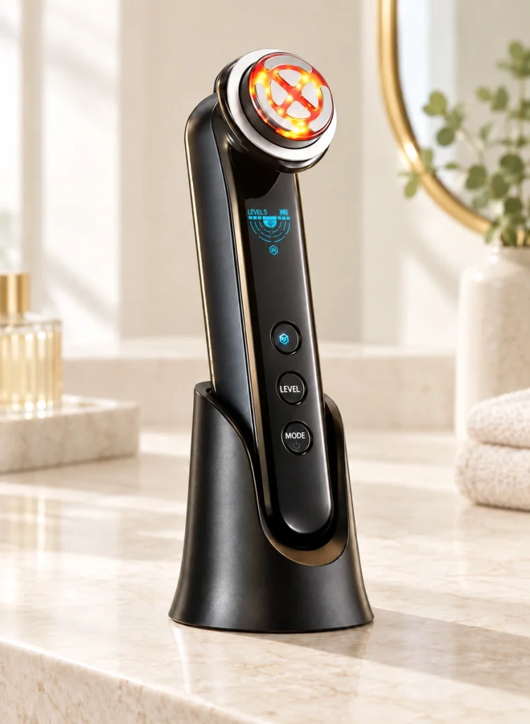
Guides, recesses, magnets or housing features can locate the contacts before the pins compress to their working stroke.
Relatively fixed geometry can help make repeated mating more consistent.
A dock may hold the device upright, set its display angle, organize the cable or provide a fixed station for charging and supported data synchronization.
For a device repeatedly docked and removed during the day, review:
Pogo-pin working stroke
Spring force
Pad position
Device weight
Docking direction
Mechanical tolerances
- Contact resistance
Use the dock's guides to position the device. The pogo pins should not be expected to correct large alignment errors.
When a Portable Magnetic Cable Fits
A magnetic cable may suit products that need portable charging in different locations.
Wearables, smart glasses, GPS trackers, compact medical products and other portable devices may charge at home, at work, during travel or from a power bank. A cable is often easier to carry than a complete dock.
Magnetic capture brings the mating surfaces together without inserting a conventional plug into the device. Touching pogo pins or flat contacts then complete the electrical connection.
A designed breakaway connection can release under a cable pull and reduce force transferred to the device. Its release behavior still needs selection and validation for the application.
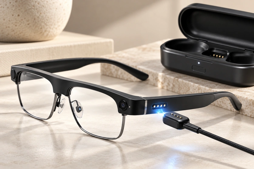
Cable motion adds requirements for:
Magnetic holding force
Breakaway force
Cable direction
Strain relief
Cable bending
Connector-head size
- 90° or 180° cable routing
These inputs matter particularly for an interface on the side of a thin wearable or handheld enclosure.
Mechanical Design Requirements
The two forms create different mechanical constraints around the device.
Dock Geometry
A dock provides a relatively fixed mating environment.
Housing surfaces, locating ribs, guides, magnets or recesses can set device position. At the intended seated position, the pins compress to maintain the electrical contact.
Resolve these four questions:
What sets the device's final stop position?
What compression will each pin reach?
How do the tolerance variations change contact force?
Is the dock stable during device placement and removal?
Keep normal pin compression within the specified working stroke rather than at full mechanical travel.
Cable-Head Integration
A cable head generally has fewer surrounding supports than a dock and moves with its flexible cable.
Account for forces associated with:
Cable weight → bending → pulling → twisting.
The transition from rigid housing to flexible cable needs attention. Suitable strain relief helps reduce loading on internal conductors and solder joints.
Cable exit direction also affects the available installation space.
A 180° outlet may suit a design with sufficient clearance behind the head.
A 90° outlet can reduce rear clearance and may fit along an enclosure's side or bottom.
Select the outlet according to the device geometry.
Sealing and Wearable Exposure
Either form can be designed to mate with a sealed device.
External contact pads can replace a deep receptacle, helping keep the enclosure closed around the interface. The actual protection depends on the completed sealing structure and its validation.
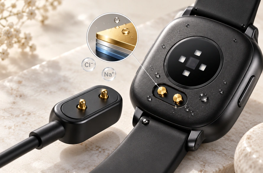
The charger side nevertheless has different mechanical requirements.
A dock usually contains its contacts in a rigid structure, limiting cable motion near the mating area.
A magnetic head is directly attached to a flexible cable. Its housing-to-cable transition must accommodate repeated bending and pulling while meeting the specified mechanical and environmental requirements.
Wearables also bring sweat and moisture exposure into the assessment.
Watches, smart glasses, fitness products and medical wearables may repeatedly expose contacts to sweat. Moisture and electrolytes can affect their surfaces over time.
Include these environmental-contact requirements:
Contact finish
Gold thickness
Barrier layers
Corrosion protection
Pad material
Compatible cleaning requirements
Environmental sealing
An IP classification does not by itself describe every contact-surface exposure. Select materials and plating for the actual environment as well as defining enclosure protection.
IP ratingFunctions Beyond Charging
The dock form does not inherently provide more electrical functions.
Charging, data, signals, identification and control depend on contact allocation and the complete circuit design. The choice of a dock or cable does not establish those capabilities.
Possible allocations include:
Two contacts primarily assigned to power and ground.
Four or five contacts with additional signal, detection or identification paths.
Six or eight contacts providing more independent control, signal or identification circuits where needed.
Compatible mechanical and electrical specifications may let the same contact arrangement be integrated into either accessory.
Define OEM functions before reviewing:
Contact count → pin assignment → current → signal requirements → mechanical structure.
Let the required device functions guide the physical form.
Choosing for Daily Use
Choose a dock where charging has a fixed location, positioning needs control or the accessory must also act as a holder or cradle.
It may suit products frequently placed and removed during normal operation.
Consider a magnetic cable for portability, several charging locations or continued use during charging where the device permits it.
It can also suit a requirement for a detachable breakaway connection.
A useful starting question is:
Does the product need a defined charging position or a flexible cable connection?
Designing One Device Interface for Both Accessories
This is possible in a coordinated design.
Some OEM designs use one device-side contact interface with both a dock and a magnetic cable.
For example, the intended use could be:
Home or office → charging dock.
Travel or backup charging → magnetic cable.
Both need compatible contact geometry, polarity, pin assignment, working compression and magnetic orientation at the device-side pads.
With those matched specifications, a manufacturer may offer both accessory forms without adding another charging interface to the device.
Matching the Accessory to the Use Pattern
Docks and magnetic cables can share conductive spring-contact technology while meeting different use patterns. Docks control position at a fixed station; cables offer portability and routing flexibility. Review product geometry, charging location, contacts, exposure and user behavior. A coordinated design may allow both accessories to share one interface.
Frequently Asked Questions
How should I compare a dock with a magnetic cable?
A dock can suit a fixed location and controlled positioning. A magnetic cable can provide portability and flexible routing. Select for the device and its charging routine rather than assuming one form is always better.
Can a charging dock use spring-loaded pogo contacts?
Yes. Within their designed stroke, pogo pins can maintain pressure while accommodating small docking tolerances. The dock still needs suitable positioning features.
Can a magnetic charging cable also carry data?
Yes, if contact allocation, wiring and the complete circuit support it. Power, signals, identification and data can be assigned according to the required functions; contact count alone does not provide a protocol.
Which form suits a wearable?
A dock may provide a regular, positioned charging station, while a cable may be easier to carry between locations. A compatible wearable can be designed for both through one contact interface.
What allows the same device to use both accessories?
Their contact positions, polarity, pin assignment, magnetic orientation and electrical specifications must be compatible. Design and verify those matches rather than judging compatibility by appearance.