
Magnetic Charging Cables: Six Benefits and the Conditions Behind Them
Published on August 26, 2026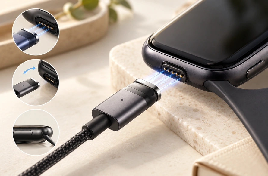
- The magnetic charging cable interface
- Limits to consider before selection
- Comparing magnetic and conventional interfaces
- When a dedicated magnetic cable may fit
A magnetic cable can assist alignment, reduce some insertion-related wear, offer a controlled release action and suit compact or frequently docked equipment. Those potential benefits depend on the mating design, retention, contacts and operating duty; they are not universal durability or safety guarantees.
The magnetic charging cable interface
Magnets positioned in or around the mating head attract the matching half within the designed capture range. Housing geometry and the magnetic arrangement help position the cable at the device interface.
magnetic charging cable interface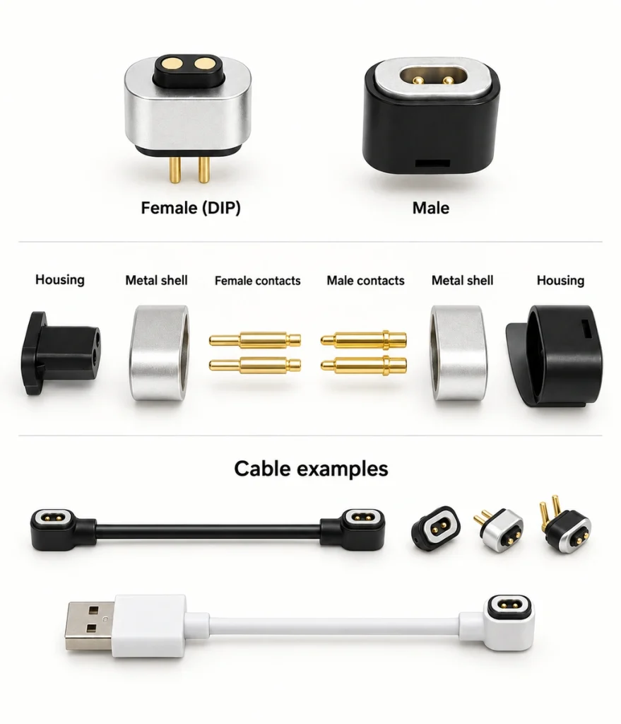
Conductive paths may use flat contacts, spring-loaded pins or another defined structure. A two-contact interface can serve a supply circuit, while additional positions allow more power and signal allocations when implemented in both mating halves.
Magnetic mating interfacesRepeatedly connected consumer products, wearables, medical equipment, handheld electronics, connected home devices and industrial equipment are possible applications. Each still needs its own electrical, mechanical and environmental review.
1. Guided attachment with less manual positioning
Magnetic guidance can make the attachment action easier for the intended user.
Plug-in USB or barrel interfaces require locating and inserting a matching plug. Some also require a particular orientation; USB-C supports reversible mechanical insertion. A magnetic interface can guide close mating halves together when its capture range and positioning features suit the device.
USB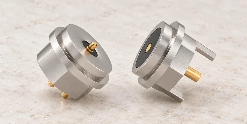
This action may be useful when a device is charged several times during the day.
Guided attachment may help where a small interface is hard to see or reach. Evaluate it with representative wearable or medical-device users and hardware; no measured speed or usability improvement is implied by the mating concept alone.
A defined magnetic polarity and mechanical positioning arrangement can help prevent incorrect engagement. Validate the electrical map rather than assuming every reversed orientation is safe.
2. Less deep-insertion stress at the device
Repeated plug insertion and removal can contribute to interface wear.
Across thousands of repeated operations, friction and handling loads may affect a plug-in connector’s shell, contacts, solder joints or surrounding enclosure. This describes a wear mechanism, not a common life rating for every USB series.
A shallow magnetic mating joint can avoid part of the repeated deep-insertion motion at a socket. Whether that improves service life depends on the complete construction and duty.
Magnets position and retain the mating surfaces, while the specified spring contacts provide conductive engagement in a spring-contact design.
A suitably validated arrangement may extend practical interface life in a frequently used dock.
Evaluate finish wear, spring construction, retention, contamination and the intended mating-cycle duty. Magnetic guidance does not remove these durability requirements.
3. A defined release action under cable pull
A magnetic joint can provide a release action that differs from extracting a plug from a socket.
An accidental pull or trip on a conventional cable may transmit force to its port and device. Depending on the arrangement, this can damage the interface or pull equipment from a desk.
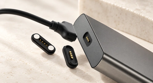
A magnetic mating pair may separate when the applied pull overcomes its retention in that direction.
Releasing without extracting a deeply inserted plug may reduce excessive mechanical loading on the device. Confirm the release behavior in the actual installation; it does not guarantee protection from every pull or fault.
Possible uses include:
Desktop electronics
Portable medical equipment
Connected home products
Charging docks for wearables
Handheld equipment
Electronics moved frequently during use
Select retention deliberately. Too little may permit unwanted separation, while too much can reduce the intended release benefit or move the device instead.
4. More options for a small or sealed interface
A magnetic mating construction can offer additional packaging choices in a compact device.
A conventional receptacle needs space for its body, insertion path, board mounting and external opening. Those four requirements can constrain a small enclosure.
PCB
A dedicated magnetic interface may use a shallower mating arrangement, with dimensions confirmed for the selected design.
One option places the magnetic spring-contact interface in the device enclosure and the matching contacts on its cable or dock.
Consider this arrangement for these application categories:
Wearables: Watches, trackers, hearing-related devices and personal electronics may have limited room for the interface. Confirm the specific product’s fit and exposure requirements.
Medical equipment: A compact device may benefit from a shallow surface that is easier to access for cleaning. Validate material and cleaning compatibility separately; the geometry does not establish sterilization suitability or medical approval.
Connected devices: Sensors, locks, handheld controllers and home electronics may use a guided dock where the required functions suit a dedicated interface.
Outdoor equipment: A magnetic interface can be integrated with a suitable sealing structure for the specified dust and water exposure.
Magnets do not make an interface waterproof. Review seals, adhesive, O-rings, contact construction and enclosure integration as a complete assembly, then verify the required ingress protection.
5. A convenient action for repeated docking
A dedicated magnetic interface may suit repeated connection to the same device.
Examples include a wearable returned to a dock each night or a handheld scanner recharged several times within a work shift. These are application scenarios, not customer case histories.
Reducing manual positioning may shorten the docking action. Confirm any speed improvement through the actual user interaction rather than assigning an unmeasured result.
Where the geometry, weight and retention permit it, bringing the mating halves close can support one-handed docking.
Evaluate this benefit against accessory compatibility. A frequently used dedicated dock may prioritize the attachment action over connection to a broad range of interchangeable cables.
6. A configurable set of electrical paths
Magnetic cable designs can use more than two charging contacts.
Additional spring-contact positions can carry separately assigned functions in a dedicated assembly.
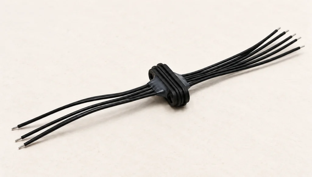
Possible functions include:
Supply paths
Return or reference paths
Implemented data communication
Charging-control functions
Device identification
Engagement or other detection signals
A two-contact example may assign one supply path and one return for charging.
Four-, five-, six- or higher-contact arrangements provide further allocation choices. Supported functions depend on the device circuit, cable and mating construction, not just the count.
An OEM pin map can follow the PCBA, battery-management system, charging circuit and communication requirements. Specify levels, references and protection alongside each function.
OEMReview seven configurable features: length, orientation, retention, spacing, housing dimensions, conductor size and opposite termination. Confirm available options for the chosen assembly.
The opposite end may use USB-A, USB-C, terminals or a dedicated connector that matches the equipment. A USB form alone does not establish PD or data capability.
Limits to consider before selection
These potential advantages do not make a magnetic cable suitable for every device.
Many magnetic interfaces are specific to a product or family. A replacement must match polarity, dimensions, contact positions and electrical configuration. Standard USB-C offers a broader defined interface, but its implemented functions and cable capability also need checking.
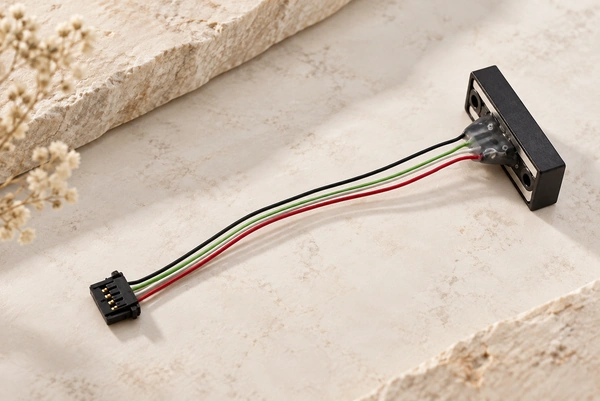
Exposed contacts can collect dust, sweat, metal particles or other contamination, affecting resistance or engagement. Include the required cleaning, protection and maintenance in the design.
Match the verified electrical rating to the load. A compact wearable interface does not inherit the current capacity of a high-power industrial assembly.
Review nine inputs before selection: current, voltage, contact resistance, retention, mating duty, sealing requirement, pin assignment, cable construction and operating environment.
Comparing magnetic and conventional interfaces
Select the approach against the device’s actual requirements.
A standard interface such as USB-C may be convenient when users connect to different compatible chargers and cables. Check supported power and data functions within that standard rather than assuming every accessory provides the same capability.
USB-C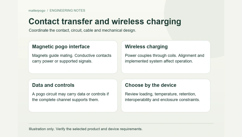
A dedicated magnetic cable may fit priorities such as frequent docking, guided attachment, less deep insertion, compact integration or a device-specific charging arrangement.
Equipment such as laptops or phones that depends on broadly available accessories may benefit from retaining a suitable standard interface.
Wearables, medical products, home equipment, docks and specialized OEM devices may benefit from a dedicated magnetic arrangement when validated for their use and exposure requirements.
When a dedicated magnetic cable may fit
Consider a magnetic cable where repeated charging, a simple attachment action, limited interface space or a dedicated device connection is a defined requirement.
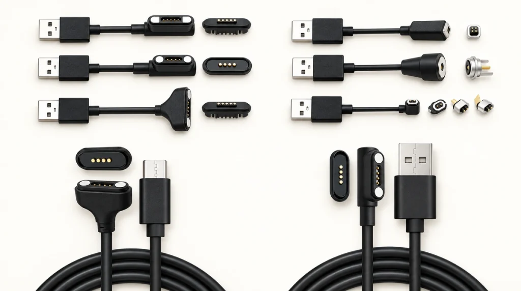
Review it as part of the product’s electrical and mechanical design rather than as an interchangeable add-on port.
Make the OEM interface decision early enough to coordinate eight inputs: dimensions, working contact height, polarity, exit direction, current rating, contact count, PCB position and enclosure structure.
With those inputs resolved and validated, the cable may simplify the device-to-charger mating arrangement while carrying the specified supply and signal functions.
A design decision with clear conditions
The six potential benefits are guided alignment, less port-insertion wear, a defined release action, repeated docking convenience, compact integration and configurable electrical paths. Their extent depends on the actual design and duty.
They can be useful where frequent attachment or a dedicated interface is central to the product.
Convenience may drive a consumer accessory choice. An OEM project can also adjust contact count, current capability, retention, dimensions, routing, sealing and the supply or signal map to its requirements. Each option needs confirmation for the chosen configuration.
A correctly specified and validated magnetic cable can offer a practical alternative to a plug-in interface. Verify compatibility, electrical load, retention and exposure before claiming reliable service in the device.