
Matching a 2 Pin Magnetic Charging Cable to Your Device
Published on September 1, 2026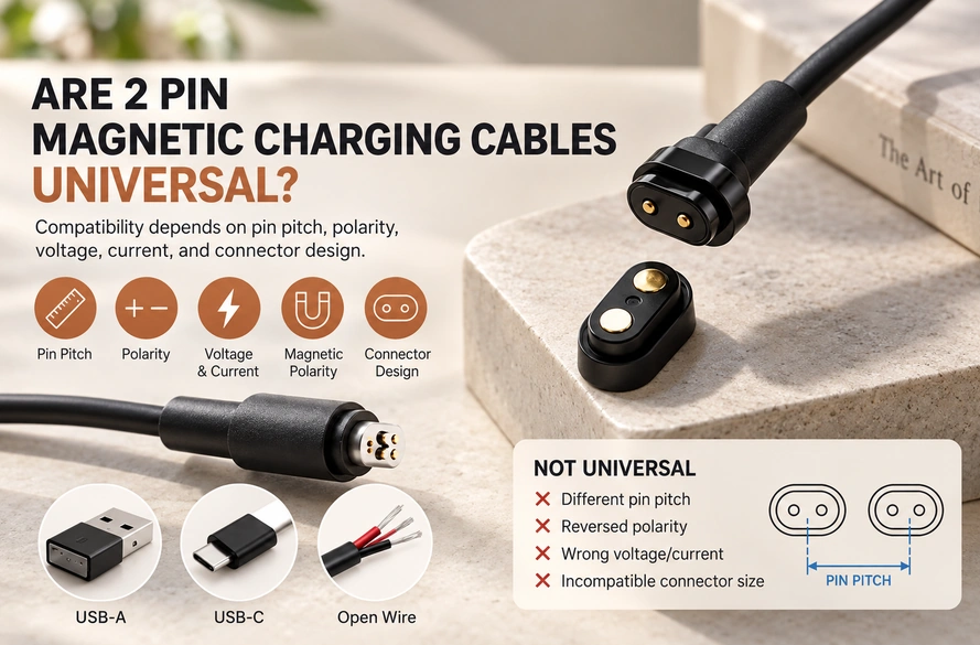
- Understanding the Two-Contact Assembly
- Why Two Pins Do Not Establish Compatibility
- Measuring and Matching Pin Pitch
- Checking Electrical and Magnetic Polarity
- Matching Voltage, Current and the USB End
- Selecting a Replacement or OEM Cable
Two-contact magnetic charging cables are not universal. Match pitch, polarity, voltage, current, dimensions, magnet orientation and working height before choosing a replacement or defining a custom OEM interface.
Understanding the Two-Contact Assembly
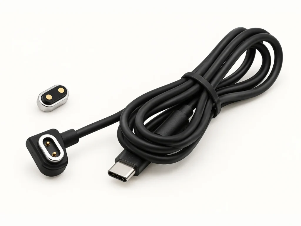
A 2 pin magnetic charging cable carries power through two conductive contacts. Magnets guide the mating parts and hold the charging head in position.
2 pin magnetic charging cableA typical DC interface assigns V+ to one contact and GND to the other. Many versions place pogo pins in the cable head and flat contact pads on the device.
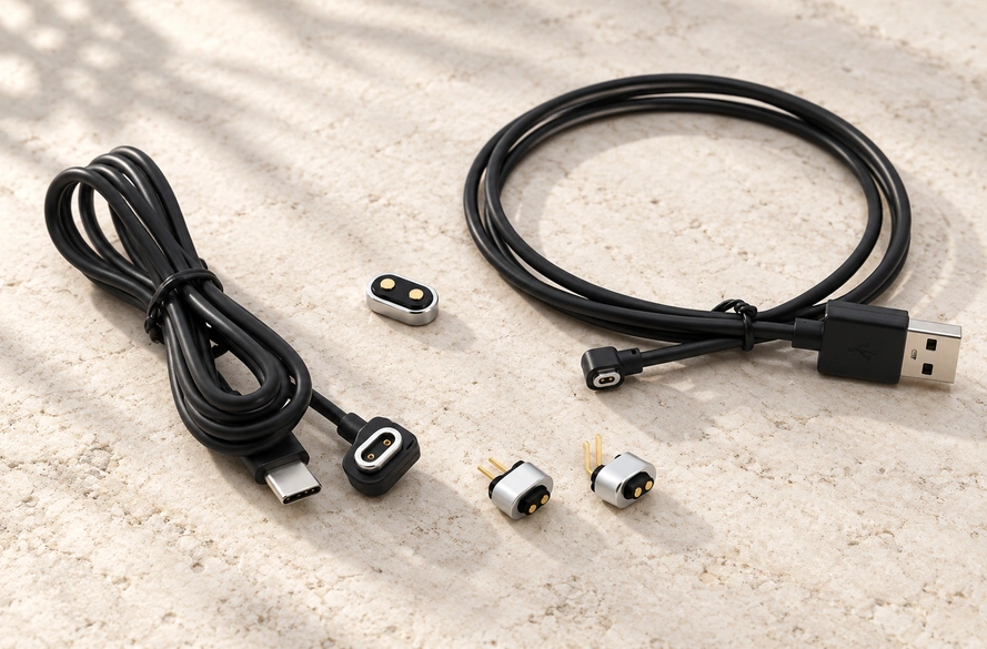
Magnetic guidance can simplify repeated docking for wearables, smart products, charging bases and portable electronics.
“2 pin” states the number of contacts, without defining the connector's size or electrical ratings.
For structure, specifications, uses and customization, consult the Magtor 2 Pin Magnetic Charging Cable Complete Guide. The 2 Pin Magnetic Charging Cable product page covers assemblies, and the 2 Pin Magnetic Connector series covers device-side connector designs.
2 Pin Magnetic Charging Cable Complete Guide2 Pin Magnetic Charging Cable product page2 Pin Magnetic Connector seriesWhy Two Pins Do Not Establish Compatibility
Two-contact magnetic cables are generally specific to their intended device interface.
The charger and product must match mechanically, electrically and magnetically. Two contacts alone do not make one cable interchangeable with another.
Two heads can both be rectangular with gold-colored contacts yet have different spacing: one might use 1.5 mm and another a wider pitch. Even if the contacts touch, reversed polarity or the wrong voltage can prevent charging or create an electrical risk.
Check the following main compatibility parameters:
| Parameter | Why It Matters |
|---|---|
| Pin pitch | Determines whether both contacts align correctly |
| Connector size | The magnetic head must physically fit the device |
| Electrical polarity | V+ and GND must match the device |
| Magnetic polarity | Determines attraction and mating orientation |
| Voltage | Must match the device charging requirements |
| Current rating | Cable and contacts must safely carry the required current |
| Pogo pin working height | Controls contact compression and reliability |
| Magnetic force | Affects retention and contact stability |
Scroll horizontally to view every column.
A replacement search based only on the phrase “2 pin magnetic charger cable” is insufficient.
Compare the proposed replacement against the original drawing or measure the device's existing interface.
For an OEM design, use PCB position, housing dimensions, the charging circuit and the needed cable configuration to define the connector.
Measuring and Matching Pin Pitch
Pitch is a key mechanical check for a two-contact charging cable.
It is measured from the center of one contact to the center of the other.
For example, centers separated by 3.0 mm indicate approximately 3.0 mm pin pitch.
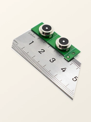
A shared contact count can still hide entirely different spacing.
A 1.5 mm cable is not normally a replacement for a 3.25 mm interface simply because each has two contacts.
Examples in the Magtor cable range include a two-contact configuration with 1.50 mm pitch and another with 3.25 mm pitch. Both have two pins, with different mechanical interfaces. View the Magtor two-contact cable specifications for the individual configurations.
View Magtor 2 pin cable specificationsUse center-to-center measurement when checking a replacement, not the gap between the edges of the contacts.
Review pitch together with contact diameter, head width, connector height and surrounding housing dimensions.
A small mismatch may leave partial rather than full contact. The head may appear attached while movement interrupts charging.
An OEM drawing should specify pitch and overall dimensions so the interface is defined by more than a two-pin label.
Checking Electrical and Magnetic Polarity
Polarity can make two visually similar pogo cables incompatible.
Evaluate two separate specifications: electrical polarity and magnetic polarity.
Electrical polarity identifies the positive-voltage and ground contacts.
One possible assignment is:
Pin 1 = V+; Pin 2 = GND.
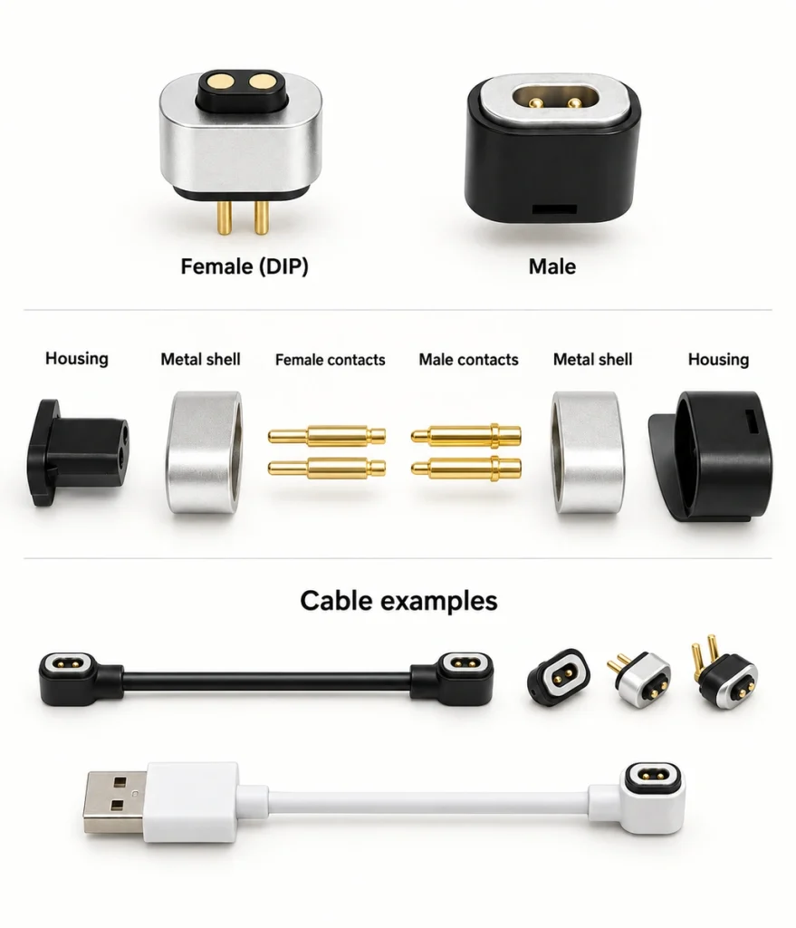
A different manufacturer's interface may assign these functions in the opposite order.
Reversed electrical polarity may make the device reject the charger. Depending on protection circuitry and the device design, it can also cause a short circuit or damage components.
Confirm polarity from the product drawing, wiring diagram, original charger specification or an electrical measurement, rather than from appearance.
Magnet orientation describes a separate property.
North and south orientations affect how the head mates. A magnetic layout may restrict the allowed direction, prevent reverse attachment or provide a specific rotational alignment.
An incompatible magnet orientation may cause repulsion or let the cable attach in an unintended position.
Coordinate the contact layout with magnet orientation in a custom interface. This can reduce incorrect mating and improve repeatability during frequent charging.
Include pin functions and magnetic polarity when ordering a custom cable; contact count and length alone do not define it.
Matching Voltage, Current and the USB End
A two-contact label does not mean that all magnetic charging cables use the same voltage.
Their voltage specifications can differ.
Contact count is independent of the specified charging voltage and power.
A device may use 5V or another DC voltage. Required current depends on its battery and charging circuit, as well as pin dimensions, contact resistance, wire gauge and thermal limits.
Match the cable to those device-side electrical requirements.
A low-current wearable cable may need a different electrical layout from one for a larger portable product.
At higher current, contact resistance deserves attention because it causes voltage drop and heat. Surface condition, spring pressure, plating, contamination, wire gauge and length can all affect charging performance.
The power-source connector is another selection factor.
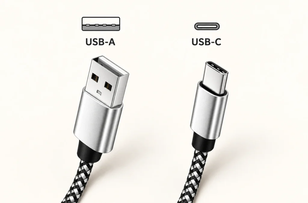
USB-A versions commonly connect to existing adapters, PCs, docks and embedded charging stations.
USB-C versions suit many newer products and supplies within the Type-C ecosystem. The USB Implementers Forum publishes the USB Type-C Cable and Connector Specification.
USB Type-C Cable and Connector SpecificationKeep the following limitation clear:
A USB-C plug alone does not establish support for USB Power Delivery or high-power fast charging in the magnetic cable.
USB Power Delivery has separate specifications and communication requirements for negotiated, flexible power delivery. The USB-IF USB Power Delivery overview describes that system.
USB-IF USB Power Delivery overviewWith two simple DC contacts at the magnetic end, capability depends on the circuits in the cable, source and product.
Choose the USB format separately from specifying current, charging protocol and maximum power.
Magtor offers USB-A, USB-C and open-wire configurations for OEM integration. The Magnetic Cable Connector series also includes multi-contact and other cable options.
Magnetic Cable Connector seriesSelecting a Replacement or OEM Cable
A replacement search and a new OEM design require different selection approaches.
When replacing a cable, use the original charger as a reference where available. Before connection, compare contact spacing, head dimensions, polarity, voltage and the current specification.
Review compatibility in the following sequence:
Pin pitch → connector dimensions → electrical polarity → magnetic polarity → voltage → current → working height.
A difference in any critical parameter calls the match into question, even if the head attaches magnetically.
This also applies to wearables. A cable marketed for a smartwatch, hearing device, tracker, smart glasses or another wearable is not a universal replacement across brands or models.
An OEM project can instead define the cable around its product, rather than start with an existing charger's geometry.
Supply PCB contact position, enclosure space, shell thickness, pitch, voltage and charging current, cable routing, magnetic force, sealing requirements, length, wire gauge and the preferred supply-end connector.
If the enclosure and PCB are already finalized, redesigning them only to fit an off-the-shelf charger may add unnecessary tooling and engineering work.
A custom cable can match the existing contacts, housing, electrical polarity, cable direction and charging requirements instead.
Magtor two-contact cables can use USB-A, USB-C or open-wire ends, with length, gauge, head dimensions and both polarities configured for the project. View the Magtor 2 Pin Magnetic Charging Cable range for these options.
MagtorFor a project also developing the device-side interface, the Magtor 2 Pin Magnetic Connector range can provide a starting point for matching both halves of the charging system.
Select a two-contact cable against its full mechanical and electrical specification. Review pitch, both polarities, voltage, current, dimensions and working height together to address compatibility and charging reliability.
Two-Contact Charging Cable Questions
What determines a two-contact cable's service life?
Pin quality, plating, spring force, alignment and connection frequency all affect life. A design intended for thousands of charging cycles still needs validation, because contamination and wear can gradually raise resistance.
Can the cable suit a water-resistant product?
Yes, with a coordinated design of the connector housing, seals, contact area and device enclosure. Define and confirm the intended IP requirement during the OEM project rather than assume it from the contact count.
Do two charging contacts provide a separate data connection?
Most such cables mainly carry power, with the two contacts assigned to positive and ground. A design needing separate data, signal or ID paths usually uses additional contacts.
How can cable length influence charging?
A longer cable can add voltage drop, particularly at higher current or with thin conductors. Evaluate length, wire gauge, current and contact resistance together for a custom assembly.
How should the contact surfaces be cleaned?
Remove power before cleaning. Keep dust, metal particles, oil and moisture away from the contacts, using a dry, non-abrasive method to avoid harming the gold finish or pogo pin surface.