
Wireless Charging or Magnetic Contacts: How to Choose the Architecture
Published on August 12, 2026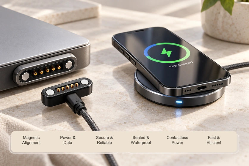
- Induction and conductive contacts compared
- Efficiency, heat and charging speed
- Sealing and packaging requirements
- Combining power with data contacts
- Benefits and limitations
- Choosing an architecture for the device
Induction avoids exposed mating power contacts, which can help a continuous-enclosure design. A magnetic connector instead carries electricity through conductive contacts and can include data paths. Compare complete systems against sealing, speed, space, signals, cost and exposure; neither mechanism guarantees better efficiency or lower heat in every implementation.
Induction and conductive contacts compared
| Feature | Wireless Charging | Magnetic Connector |
|---|---|---|
| Power transfer | Electromagnetic induction | Direct electrical contact |
| Charging efficiency | Depends on coil coupling, controls and load | Depends on contact loss, cable and power controls |
| Heat generation | Depends on transfer losses and thermal design | Depends on resistance, load and thermal design |
| High-current support | Requires a suitable coil and power-electronics design | Requires suitable contacts, conductors and thermal validation |
| Data transmission | Power-control communication is distinct from an application-data interface | Power and data are possible with the specified pinout and circuit |
| Waterproof design | Can avoid power-contact penetrations; validate the whole enclosure | Contact and enclosure interfaces need appropriate seals |
| Internal space | Requires coils and electronics | Compare the whole contact, magnet and control assembly |
| Alignment | Coil position matters; magnetic alignment can also be used | Magnetic guidance needs suitable housing geometry |
| Customization | Coils, structure and controls can be tailored within system requirements | Contacts, housing and magnetic layout can be customised |
| Cost | Depends on coils, electronics, tooling and volume | Depends on contacts, seals, tooling and volume |
Scroll horizontally to view every column.
Efficiency, heat and charging speed
A conductive contact path can avoid the additional transfer stage between inductive coils. Its actual losses still depend on contact resistance, cables and power controls. Fast charging or high current requires a rated and validated electrical design; the magnetic coupling does not supply that capability by itself.
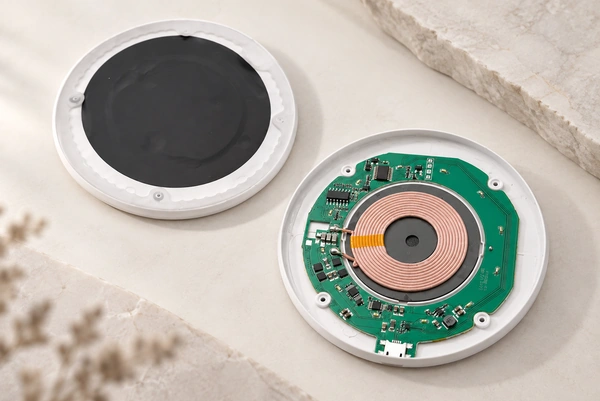
magnetic contact interfaceInduction uses transmitter and receiver coils. Separation or misalignment can affect coupling, loss and heat, while suitable magnetic alignment can help position the coils.
Inductive chargingFor industrial, medical or handheld products, compare measured system efficiency and charging time under the intended conditions. The application category alone does not make conductive charging the better option.
Sealing and packaging requirements
Induction can remove exposed charging contacts and their enclosure penetrations. That can simplify a continuous exterior, but materials, seals, thermal behaviour and the final ingress conditions still require validation.
Watches, rings, other wearables, outdoor products and some medical devices are possible applications for that arrangement, with device-specific requirements.
A magnetic contact assembly can also form part of a sealed design using suitable housings, adhesive interfaces or O-rings. Exposed-contact corrosion and wet operation need their own assessment, separate from water entering the enclosure.
O-rings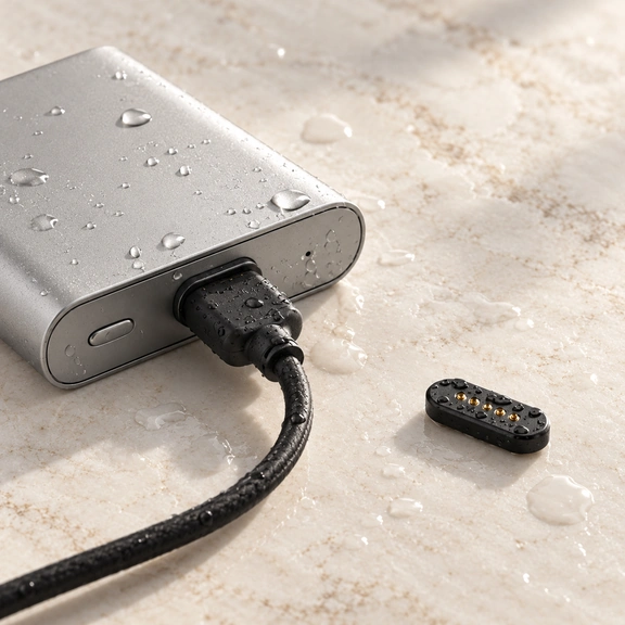
A small contact layout may fit a constrained product, but compare the complete magnet, contact, mounting and electronics envelope with the complete inductive system. Comparing a loose connector with an entire coil assembly is insufficient.
PCBCombining power with data contacts
Yes, where the interface and electronics are designed for the required functions.
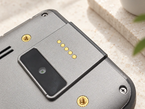
A multi-contact layout can assign conductors to:
Power; ground and return paths; data; other signals
For example, five contacts can serve charging with signals or detection in a specified circuit. They do not automatically support USB, Power Delivery or a particular data rate.
five-contact magnetic connectorWireless charging also exchanges control information; that is distinct from a general application-data connection. An inductive power interface alone normally does not replace a dedicated signal interface for the product’s regular communication needs.
Scanners, medical devices, cameras, robots, test equipment and smart electronics may benefit from separate conductive signal paths where their circuit requires them. Validate the actual power and communication interface.
Benefits and limitations
Potential inductive benefits: no exposed mating power contacts, fewer contact penetrations to seal, convenient placement and no electrical-contact wear. The rest of the system can still age or wear, and the complete product needs its sealing validation.
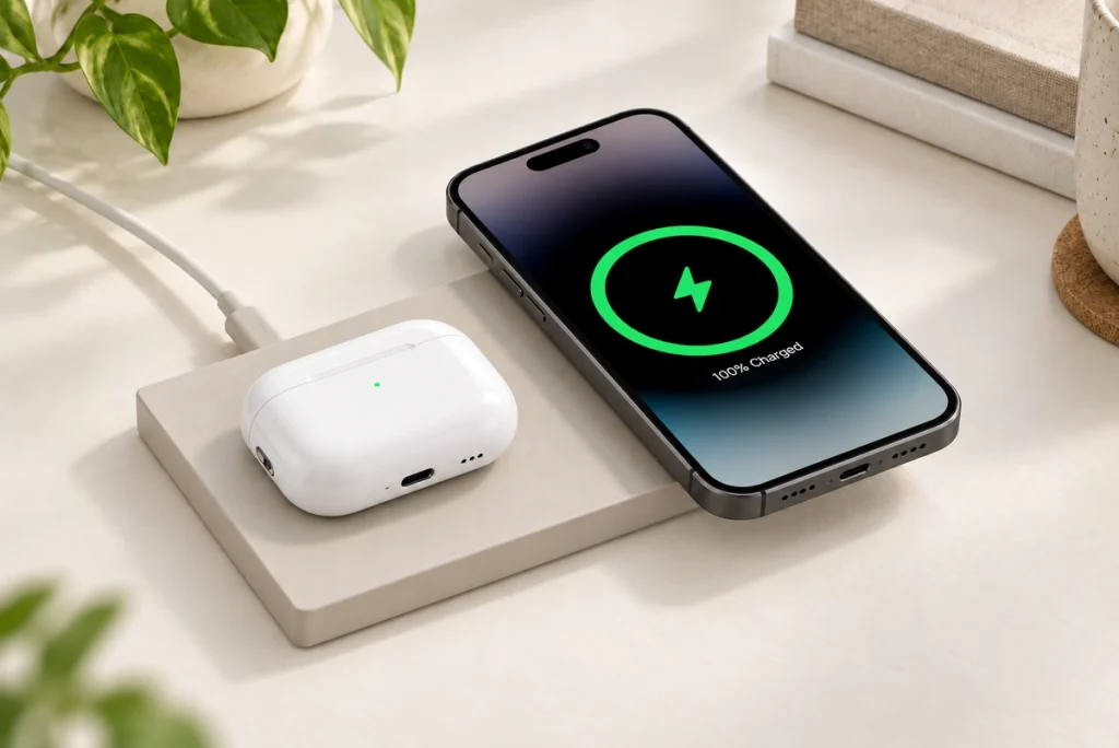
Inductive considerations: transfer losses, heat, coil alignment, coil and electronics space, circuit complexity and the distinction between power control and application data. Magnetic positioning can assist alignment in suitable wireless designs, including Qi2 MPP.
Potential magnetic-contact benefits: a direct conductive path, custom packaging, guided attachment and contacts allocated to power and signals. High-current capacity, low losses, low heat and simultaneous data operation all depend on the chosen design and validation.
Magnetic-contact considerations: sweat, dust, moisture and corrosion can affect exposed surfaces. Select plating, seals, materials, maintenance and power control for the actual environment rather than relying only on an IP label.
Choosing an architecture for the device
Consider induction where the priorities include:
A continuous enclosure with appropriate sealing
No exposed electrical contacts
A consumer product with defined ingress requirements
Contactless charging experience
Consider a magnetic contact interface where the priorities include:
A conductive charging path with validated efficiency
Specified fast-charging or high-current requirements
Power and data transmission
Compact connector size
Custom dimensions and pin configurations
Controlled losses and a suitable conductive power path
Induction can suit phones, watches and sealed wearables; conductive magnetic contacts can suit products that need guided docking and defined power or signal paths. Industrial, medical and robot applications can use either approach when the full requirements and tests support it.
Conclusion
Select the architecture for the application rather than declaring a universal winner.
Induction is worth considering where removing exposed contacts is important. Conductive magnetic contacts are worth considering where custom packaging, controlled current paths or combined power and signals matter. Efficiency, heat and speed must be compared using complete designs.
Decide from the required power, ingress conditions, available space, data interface, charging frequency and target cost, with the relevant validation evidence.
Frequently asked questions
Which charging interface lasts longer?
Induction avoids wear at mating power contacts. A magnetic-contact system depends on the spring structure, plating, working force and use conditions. Both can be designed for the required life, but compare defined tests rather than assuming a general lifespan ranking.
What can be customised in a magnetic interface?
Contact count and pitch, housing shape, retention and release force, mounting, cable exit and electrical requirements can be tailored to the device. Review the geometry, tolerances and circuit as part of the proposed design.
How do dust and sweat affect the two approaches?
Without exposed power contacts, induction avoids direct contamination of that conductive interface, but the product still faces environmental and thermal requirements. Magnetic contacts need suitable finishes, seals and corrosion assessment for dust, humidity or sweat.
Can either approach support automatic docking?
Yes. A contact dock can use magnets and mechanical guidance; an inductive dock can also use magnetic coil positioning. For robots, scanners or industrial docks, verify the capture range, placement tolerance and complete power behaviour rather than assigning alignment exclusively to one technology.
What should the validation plan cover?
Check charging temperature, efficiency, alignment tolerance, ingress protection, environmental exposure, life and compatibility in the complete system. For contacts, also monitor resistance and mating durability, with defined test conditions and acceptance criteria.