
Charging Contact Corrosion: Mechanisms and Design Responses
Published on September 7, 2026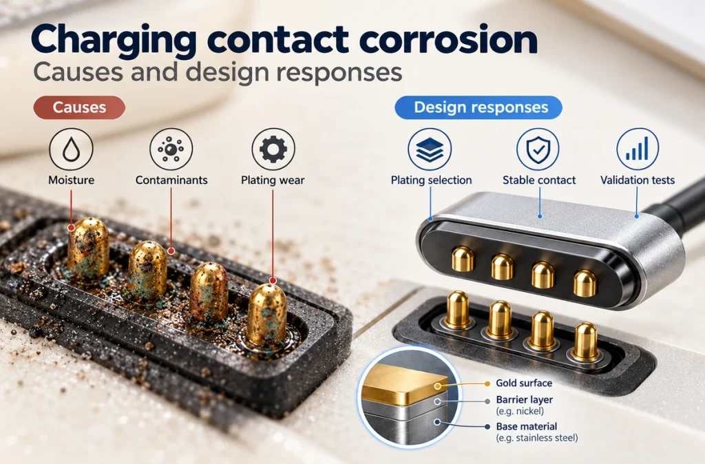
- Contributing Causes
- Moisture, Sweat and Contamination
- Why a Gold Finish Can Still Fail
- Fretting at the Contact Pair
- Effects on Charging
- Reducing Corrosion Risk
- When Replacement or Redesign Is Needed
Moisture, salts, contamination, worn plating and electrical potential can expose reactive contact metals to corrosion. The resulting rise in resistance may make charging unstable. Review plating, pressure, moisture management and validation together to reduce risk.
Contributing Causes
Environmental exposure and mechanical wear commonly act together in charging-contact corrosion.
Moisture, sweat, salt, dust, skin oils and other contamination may remain on exposed surfaces. Repeated charger-to-device mating also wears the finish through mechanical contact.
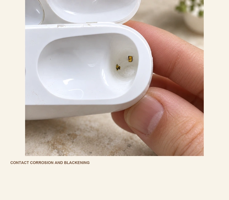
Damage to the protective finish or exposure of the base material can make oxidation and other corrosion reactions more likely.
Contributing factors include:
Moisture and high humidity
Sweat and salt residues
Seawater or chloride-containing liquids
Dust and surface deposits
Repeated mating and wear
Pores, scratches or inadequate plating thickness
Vibration and small relative movements
Electrical potential across wet contacts
On a wearable, retained sweat or seawater can act as an electrolyte when DC voltage is applied at charging contacts, creating conditions for electrolytic corrosion.
electrolytic corrosionMoisture, Sweat and Contamination
Moisture can support oxidation of exposed metals. Dissolved salts can make liquid exposure more problematic, depending on material, concentration and operating conditions.
Sweat contains ions and chloride-containing salts. Evaporation can leave salt residues around the contacts, which may become conductive again when moisture is present.
Watches, fitness trackers and other wearables need attention because their charging areas often sit near or against skin.
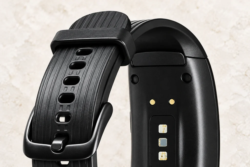
A conductive liquid bridging positive and negative contacts can serve as an electrolyte under applied voltage. The contacts can then act as anode and cathode, promoting electrolysis-related corrosion.
Particles can interrupt metal contact and add wear. Published work on gold-plated connectors under specific particle and fretting conditions reports accelerated coating wear, exposed nickel or copper and higher resistance; those findings do not represent every pollutant or connector.
Electrical performance may deteriorate before heavy corrosion is visible.
Why a Gold Finish Can Still Fail
Gold provides an oxidation-resistant conductive surface, which makes it useful for contacts. A plated contact, however, also contains other materials beneath that surface.
One possible layer arrangement is:
Gold surface layer → nickel barrier → copper alloy or another base material.
The gold layer protects the substrate only while its condition provides the intended barrier.
Repeated mating wears the gold finish; scratches, pores and local damage can expose nickel or copper-based layers.
Moisture and salts can then reach those more reactive materials and permit corrosion.
Research on gold-plated contacts describes fretting that wears through a finish, followed by oxidation and worsening resistance. The outcome depends on the tested contact and motion conditions.
The words 'gold plated' alone are therefore insufficient to assess a charging contact.
Review:
Plating thickness
Barrier-layer design
Surface porosity
Plating hardness
Wear resistance
Base material
Expected mating cycles
Application environment
A multilayer or composite finish can be developed for sweat, moisture and frequent mating. Its corrosion, wear and electrochemical resistance must be assessed for the particular materials and operating conditions.
Fretting at the Contact Pair
Small repeated relative movement between touching conductive surfaces can wear their finish and enable fretting corrosion.
Fretting corrosionVibration, thermal expansion, dimensional variation or unstable mechanical loads may drive that movement.
Although the movement can be very small, repeated cycles may accumulate surface damage.
A possible degradation sequence is:
Micro-movement → plating wear → base-metal exposure → oxidation → wear debris → higher resistance.
Fretting studies describe insulating oxides forming at an interface and increasing resistance. Gold-plated contacts can also deteriorate after motion removes their protective finish.
In a published electroplated-gold contact experiment, motion displaced gold, exposed nickel and then brass, and accumulated oxidized wear particles alongside a sharp resistance rise. That sequence describes the experiment's conditions, rather than a universal service-life prediction.
Evaluate fretting as well as environmental corrosion in vibrating equipment or designs that dock repeatedly.
Effects on Charging
Corrosion affects more than surface appearance.
Charging requires a stable, low-resistance connection. Oxides, corrosion products and deposits can reduce the effective metal-to-metal contact area and disrupt that connection.
Possible outcomes include:
| Contact Condition | Possible Charging Result |
|---|---|
| Surface contamination | Intermittent charging |
| Oxide or corrosion deposits | Increased contact resistance |
| Worn plating | Faster corrosion of underlying metal |
| Uneven pogo pin contact | Unstable current |
| Severe surface damage | Charging failure |
| High contact resistance | Voltage drop or localized heating |
Scroll horizontally to view every column.
Under fretting and corrosion, resistance can fluctuate or rise as damage develops. This can reduce the reliability of the contact pair.
Temporary improvement after repositioning, appropriate pressure or cleaning may point to a deteriorating interface, rather than the supply alone. Follow the manufacturer's instructions and check other causes as well; this observation is not a diagnosis or a reason to repair energized contacts.
Reducing Corrosion Risk
Treat the contact pair as a complete electrical and mechanical system. A protective coating is one part of its corrosion control.
Specify the Plating Stack
Gold can reduce oxidation risk, but thickness, barrier layers, hardness and wear resistance must suit the operating environment.
For repeated sweat or moisture exposure, consider a multilayer finish selected for wear, sweat corrosion and powered electrolysis resistance. Validate that combination under the intended conditions.
Base the finish on expected mating cycles and exposure instead of surface appearance alone.
Maintain the Intended Contact Pressure
In a pogo interface, spring force and working stroke determine how the contacts engage.
Insufficient compression may lead to:
Low contact force → intermittent contact → higher resistance.
Excessive compression may instead lead to:
High mechanical load → faster surface wear → reduced plating life.
Design for suitable pressure across the required product life, then verify that target.
Manage Retained Liquid
Reduce housing cavities and surfaces that hold sweat or water beside exposed contacts.
For skin-contact and outdoor equipment, assess pad locations, drainage, spacing and surrounding geometry early in mechanical development.
An IP-rated housing may protect electronics from specified ingress, yet exposed charging contacts still need suitable corrosion-resistant materials and interface geometry.
IP-rated enclosureControl Mating Alignment
Misalignment can leave partial contact or cause unnecessary lateral sliding.
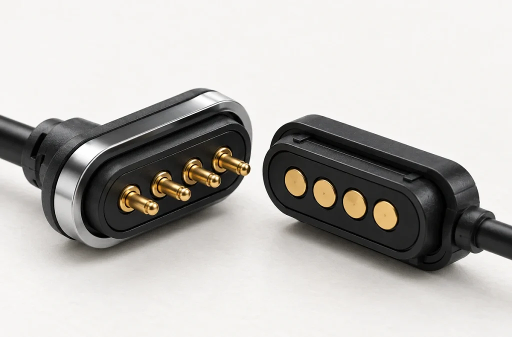
A Magnetic Cable Connector can guide its head toward the mating position with magnets while pogo pins provide conduction.
Magnetic Cable ConnectorCoordinate retention force, magnet orientation, working stroke and housing tolerances as one design.
Avoid Energizing Wet Contacts
Where feasible, the device should prevent charging voltage being applied across sweat or conductive liquid at the contacts. Users should disconnect and fully dry the interface as instructed before charging.
This matters especially for wearables because energized wet contacts can support electrolysis.
For wearable-specific design measures, see Reducing Corrosion Risk at Wearable Charging Contacts.
Validate Before Production
Mechanical and environmental validation can reveal risks before deployment in the field.
Methods to consider include:
Salt spray exposure
Artificial sweat exposure
Controlled powered-electrolysis testing
Mating-cycle testing
Contact-resistance measurement
Pogo pin spring-force testing
Plating-thickness inspection
Visual surface inspection
ASTM B117 describes a controlled salt-spray environment for evaluating relative corrosion resistance of metals and coatings. Salt-spray results alone should not be used to predict real-world service life, so include application-specific validation.
ASTM B117 salt spray testingFor a wearable, artificial sweat with applied power examines mechanisms that an unpowered salt-spray test may not cover. Define the solution, electrical load and exposure conditions for the laboratory program.
When Replacement or Redesign Is Needed
Light deposits do not necessarily mean permanent failure. If the plating and mechanism are intact, manufacturer-approved cleaning and complete drying with power disconnected may restore contact; cleaning cannot rebuild worn plating.
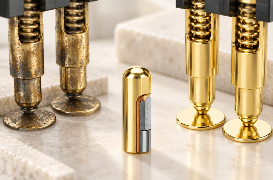
Consider replacement or redesign for:
Severe pitting
Peeling or worn-through plating
Exposed base material
Persistently elevated resistance
Stuck or damaged pogo pins
Reduced spring force
Intermittent charging that persists after cleaning
Corrosion recurring in normal use
Repeated field failures call for investigating why the interface permits corrosion, rather than relying on repeated cleaning.
Possible contributors are plating choice, spring force, geometry, liquid retention, electrical behavior and insufficient environmental validation.
Designing for the Combined Stresses
Charging interfaces encounter both environmental exposure and mechanical stress.
Moisture, sweat, salts and deposits can affect exposed metal while mating and fretting wear its finish. Exposed underlying materials may then oxidize or react electrochemically, increasing resistance and causing unstable charging or failure.
Combine an appropriate finish, stable pressure, controlled wear, liquid management and application-specific testing to reduce corrosion risk.
For a compact product, specify contact count, spacing, magnetic force, plating and environment together. A 2 Pin Magnetic Charging Cable can serve suitable charging-only designs; a multi-contact Magnetic Cable Connector can support power, data or identification when the complete device interface is designed for those functions.
2 Pin Magnetic Charging Cable