
Two-contact Magnetic Connectors: A Selection Guide
Published on June 26, 2026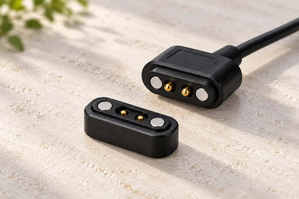
- What a Two-contact Magnetic Connector Contains
- How the Two Halves Engage
- Common Two-contact Interface Arrangements
- Electrical and Mechanical Specifications
- Application Examples
- Potential Benefits of Two Contacts
- Selection Checklist
- Reasons to Consider Magnetic Attachment
- Common Questions
A two-contact magnetic interface provides two conductive paths with magnetic guidance and retention. It may suit power connections in consumer electronics, industrial equipment, medical devices, LED lighting and IoT products when the design meets their requirements. This guide covers operation, interface arrangements, specifications, applications and selection checks for engineering and procurement.
What a Two-contact Magnetic Connector Contains
The assembly normally combines two conductive contacts, magnets and a supporting housing. Magnets and housing geometry locate the mating faces, while the contacts establish the electrical paths. A common DC assignment uses one positive supply contact and one ground or return contact; verify the actual drawing and polarity.
two-contact magnetic connector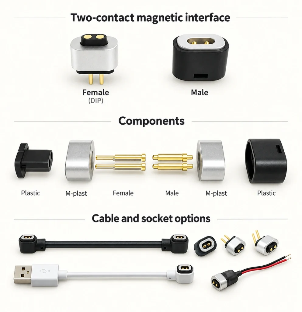
With only two conductive paths, typical functions to evaluate include:
DC power transfer.
A suitable low-voltage circuit.
Battery charging through the required charging electronics.
Simple signal switching where the circuit supports it.
An LED power supply connection.
A two-path structure can use less space and fewer contact parts than a comparable higher-count arrangement. Actual size, manufacturing effort and cost still depend on its current, materials, sealing and mounting requirements.
How the Two Halves Engage
The interface has two matching assemblies, often described as:
The male half.
The female half.
The intended mating sequence is:
Bring the correctly oriented halves together so the intended magnetic poles attract.
The magnetic arrangement and locating geometry align the contacts.
Spring compression and the designed retention hold the electrical engagement.
Current passes through the two assigned contact paths.
Separation opens those paths; the product must handle disconnection as specified.
Additional design options may include:
A defined sealing structure.
Retention or support designed for vibration.
Gold-plated mating contacts.
Larger or otherwise suitable high-current terminals.
Each option addresses a particular requirement. Verify its performance in the final portable or industrial assembly rather than assuming that an added feature guarantees reliability.
Common Two-contact Interface Arrangements
The suitable structure depends on the application. Housing appearance and connector geometry may also be adapted to the device, subject to manufacturing and validation requirements.
1. Magnetic Mating
Magnets guide the contact faces into their intended position and retain the engaged assembly.
magnetic connectorPotential benefits include:
Quick blind mating within the specified approach range.
Less insertion-related mechanical wear.
Convenient one-handed attachment where the product supports it.
A mating-life target suited to frequent use.
A designed quick-release action at the specified force and direction.
Application examples:
Smart wearables.
Smart mugs.
Charging docks.
Medical devices.
Portable electronics.
2. Wire-to-wire Arrangement
This arrangement joins two cable assemblies through the specified mating interface.
Application examples:
Home appliances.
Automotive wiring.
LED systems.
Industrial equipment.
3. Wire-to-board Arrangement
This arrangement links a cable to a PCB-mounted interface.
Application examples:
Consumer electronics.
Battery packs.
Small appliances.
IoT devices.
4. Sealed Two-contact Arrangement
A sealing structure protects the specified parts from the defined moisture, dust or contamination exposure. Its protection depends on the relevant assembly state and test evidence.
Possible protection targets include:
IP65.
IP66.
IP67.
Application examples:
Outdoor lighting.
Marine equipment.
Agricultural machinery.
Industrial automation.
Electrical and Mechanical Specifications
Choose specifications from the actual operating scenario and review the associated cost. The ranges below are examples from the design discussion, not a combined rating for one product or a guarantee applicable to every two-contact interface.
| Specification | Illustrative range or target to verify |
|---|---|
| Contact count | 2 |
| Current rating | 1A–30A, depending on the specific design and thermal conditions |
| Voltage rating | 12V–250V appears in the source range; any selected rating requires model-specific insulation and safety evidence, especially for accessible contacts |
| Contact resistance | <30 mΩ as an example target |
| Insulation resistance | >100 MΩ as an example target |
| Operating temperature | −40°C to +85°C, or higher only for an appropriately rated design |
| Mating cycles | 10,000–100,000+ as a model-specific life target |
| Water-protection rating | IP65–IP68 for a suitable tested sealing arrangement and state |
Scroll horizontally to view every column.
Obtain the chosen model’s exact specification and test conditions; these examples must not be combined into an assumed universal rating.
Application Examples
Two contacts may suit equipment with a small interface area or only a limited electrical-function requirement. Suitability still depends on the contact assignment, operating load and exposure.
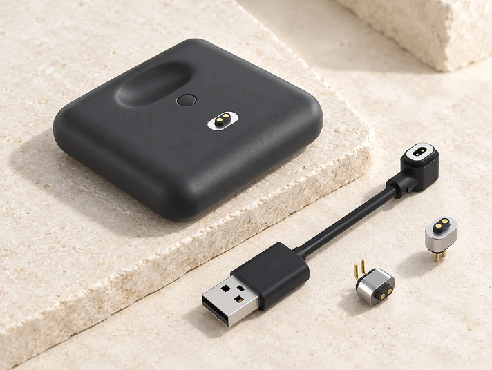
Consumer Electronics
Product examples:
Smart speakers.
Tablets.
Charging docks.
Portable devices.
Power banks.
Wearables
Compact charging interfaces may be useful in:
Smartwatches.
Fitness trackers.
Health-monitoring wearables.
AI smart glasses.
A magnetic two-path charging face can simplify attachment on a smartwatch or smart-glasses frame. Check its size and mass against the product’s space and comfort requirements rather than assuming the weight contribution is negligible.
Two-contact magnetic connectorsMedical Equipment
Medical applications need the specified repeatability and electrical reliability, together with relevant product qualification.
Application examples:
Portable monitors.
Diagnostic equipment.
Rehabilitation devices.
Charging stations.
A suitable gold-plating system can support stable mating contact, but the complete contact and cleaning exposure still require validation.
Industrial Equipment
Industrial service may place demanding loads and exposure on the interface.
Equipment examples:
Sensors.
Handheld terminals.
Industrial controllers.
Inspection instruments.
Sealing and vibration-resistant support are options to specify where the actual industrial conditions require them.
LED Lighting
A two-path power interface can be considered for:
LED strips.
Architectural lighting.
Commercial lighting.
Outdoor lighting with the required environmental protection.
Potential Benefits of Two Contacts
Compared with an otherwise similar higher-count system, a two-contact arrangement can offer these potential benefits:
A Simple Contact Arrangement
Fewer contact parts can reduce manufacturing complexity, although reliability depends on the full assembly and its controls.
Cost-conscious Construction
Fewer contacts may reduce material and assembly cost. Compare actual quotations for the required current, sealing and mounting rather than assuming a universal price advantage.
Compact Geometry
Two conductive paths can fit a small interface when their required dimensions and spacing suit the device.
A Defined Power Path
A correctly designed positive-and-return pair can transfer the required current with contact resistance within its specified limits.
Straightforward Integration
Some mating interfaces connect without special tools in use, while installation and termination may still require the specified assembly equipment.
Repeated-mating Capability
Suitable plated-contact designs may target tens of thousands of cycles. Confirm the life test and allowed performance change for the selected model.
Selection Checklist
Start with the application requirements; choosing two contacts does not complete the connector specification.
1. Current Capacity
Select a model that meets the maximum operating and transient load under the actual duty cycle and thermal conditions. Agree any design margin and verify temperature rise rather than relying on a higher label alone.
2. Operating Voltage
Verify insulation, spacing and accessible-contact protection for the working voltage and application requirements.
3. Exposure Conditions
Define whether the product encounters:
Outdoor exposure.
High humidity.
Dust.
Oil.
Other chemicals.
Review sealing, corrosion resistance and high- and low-temperature limits for those conditions.
4. Mechanical Life
For frequent mating, specify a contact and assembly life target. The source example for standard pogo designs is 10,000–50,000 cycles; a longer target may need a different or custom design. Use model-specific test results rather than treating that range as a standard applicable to every pogo contact.
5. Dimensions and Appearance
Check mechanical fit and the accessible mating face, as well as how the interface integrates with the product’s intended appearance.
6. Mounting Method
Mounting options may include:
SMT termination.
Through-hole termination.
Cable assembly.
Panel mounting.
7. Customization Inputs
Parameters to discuss with the manufacturer include:
Contact pitch.
Magnetic holding and release force.
Contact-coating system.
Cable length.
Housing material.
Sealing structure.
Verified current capacity.
Connector geometry.
A custom structure can improve fit with the product requirements when the changes are manufacturable and validated.
Reasons to Consider Magnetic Attachment
Magnetic attachment can simplify quick connection and guide the mating faces as they approach. Standard tooling may also help development timing and cost for a suitable design, but customization cost and production speed depend on the actual project rather than the use of magnets alone.
Potential handling benefits include:
Magnetic alignment assistance.
Lower insertion effort.
Less insertion-related contact wear.
Convenient connection in the intended product.
A quick-release response where designed and validated.
Reduced load from accidental cable pulls within the tested release behavior.
These features make a magnetic two-path interface worth evaluating for repeated charging, provided it also meets the electrical, mechanical and exposure requirements.
Common Questions
What Functions Can Two Contacts Provide?
Two paths can carry power or a simple electrical function assigned by the circuit design. Examples include charging, LED supplies, battery interfaces and suitable medical or industrial equipment; they do not provide separate power and multiple data paths automatically.
Can a Two-contact Design Carry High Current?
Some purpose-designed interfaces may target 10A to more than 30A. Contact dimensions alone do not prove that capacity: verify the complete assembly’s current rating, resistance, duty cycle and temperature rise.
Is Every Two-contact Magnetic Interface Sealed?
No. Suitable models may use sealing structures tested for IP65, IP67 or IP68 in a specified assembly state. Confirm the protected parts and actual exposure conditions for outdoor or industrial use.
How Does a Two-contact Magnetic Interface Differ from USB?
A conventional USB plug uses mechanical insertion, while a magnetic interface uses magnetic guidance and face contacts. The two-contact charging example supplies power and return; USB describes separate interface and protocol requirements. Compare supported functions and validated life rather than assuming all magnetic designs outperform USB.
Which Parameters Can Be Customized?
Subject to the manufacturer’s capability, options may include current rating, cable length, housing material, magnetic force, coating thickness, sealing target, dimensions and mounting. Agree the exact requirements and validation plan for the revised design.
Conclusion
A two-contact structure can provide a compact power interface when it matches the application. Magtor brings more than a decade of connector experience to discussions spanning consumer and wearable products, industrial automation and medical-device projects. The chosen design still needs validation against the equipment’s electrical, mechanical and environmental requirements.
MagtorShare the electrical load, protection target, mating life and integration details with Magtor to discuss a suitable standard or custom interface. The team can review design and production requirements with you; the final specification, evidence and commercial terms must relate to the actual connector and project.