
12 Magnetic Connector Design Mistakes to Check Before Production
Published on August 5, 2026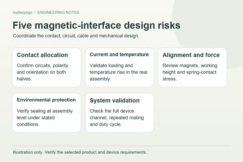
- What is the main selection mistake?
- Twelve application mistakes at a glance
- 1. Selecting by pin count alone
- 2. Treating a 3 A rating as a device guarantee
- 3. Choosing excessive magnetic force
- 4. Relying on magnets for final alignment
- 5. Expecting pogo pins to correct any assembly error
- 6. Confusing connector IP67 with device IP67
- 7. Treating all gold plating as equivalent
- 8. Mating or separating without live-power protection
- 9. Making pogo pins carry mechanical loads
- 10. Assuming all contacts mate together
- 11. Assuming more pins support any data interface
- 12. Approving production from one sample
- How to specify the complete interface
- Checks before design approval
A magnetic interface can make a device easier to connect, but poor integration can still cause overheating, intermittent contact, leakage, communication faults and early wear. These twelve design mistakes explain why the complete application needs attention.
Magnetic interfacesWhat is the main magnetic-connector selection mistake?
The central mistake is assessing the connector on its own while overlooking the device, cable and operating conditions around it.
Magnets, spring contacts, contact pads, housings, mounting features, cables, PCB connections and seals must work together. A suitable individual component does not establish the performance of that assembled interface.
PCBA working prototype can still encounter problems in production, including:
Insufficient pogo pin compression
Excessive assembly tolerance
Incorrect current allocation
Misalignment during mating
Water entering from the rear side
Contact corrosion caused by sweat
Electrical arcing during live disconnection
Incorrect magnet polarity
Side loading on the pogo pins
Start selection with a specification for the whole application; connector dimensions are only one part of it.
Twelve magnetic-connector application mistakes
| Application mistake | Possible problem | Recommended approach |
|---|---|---|
| Selecting only by pin count | Incorrect power, ground, signal, or detection pin allocation | Define each pin function before selecting the connector |
| Using the rated current as the guaranteed device current | Excessive voltage drop, heating, or contact damage | Verify continuous current, peak current, temperature rise, and PCB capacity |
| Choosing the strongest possible magnet | Difficult separation, impact damage, and cable stress | Match magnetic force to device weight, orientation, and release requirements |
| Relying only on magnets for alignment | Offset mating, unstable contact, and side loading | Add mechanical guides, positioning features, and anti-reverse structures |
| Expecting pogo pins to absorb all assembly tolerance | Insufficient compression, over-compression, or pin damage | Control working height and tolerance within the recommended compression range |
| Assuming a waterproof connector makes the device waterproof | Water enters through the housing, cable outlet, or PCB side | Validate sealing at the complete device level |
| Assuming gold-plated contacts cannot corrode | Rising contact resistance after sweat, salt spray, or abrasion | Specify plating structure, thickness, and environmental testing |
| Allowing uncontrolled live mating | Arcing, inrush current, contact burning, or device restart | Add current limiting, detection pins, soft start, or delayed power control |
| Using pogo pins as mechanical supports | Bent pins, sticking pins, and reduced service life | Use the housing to carry positioning and mechanical loads |
| Assuming every pin contacts simultaneously | Incorrect power-up sequence or temporary short circuit | Design contact sequence through pin height or circuit control |
| Using a multi-pin connector for any data signal | Crosstalk, EMI, packet loss, or unstable communication | Evaluate signal integrity, grounding, shielding, and pin arrangement |
| Approving mass production after a simple sample test | Failures caused by accumulated dimensional tolerance | Conduct pilot production and reliability validation |
Scroll horizontally to view every column.
1. Why is pin count alone insufficient?
A typical initial request might read:
“We need a five-pin magnetic connector for a 3 A charging application.”
five-pin magnetic connectorThat describes a starting requirement, but it does not establish the necessary pinout or operating conditions.
Five contacts can serve quite different arrangements, for example:
Two power pins, two ground pins, and one detection pin
One positive pin, one ground pin, and three signal pins
Two charging pins, two data pins, and one device-identification pin
One power pin, one ground pin, and three reserved pins
Define the following before choosing a connector:
Continuous and peak current
Operating voltage
Power and ground allocation
Signal type
Detection or identification requirements
Future expansion requirements
Contact sequence
Required safety spacing
Pin count tells you how many contacts are available. Whether those contacts can support the application depends on their functions, spacing and electrical limits.
2. Does a 3 A connector rating guarantee 3 A in the device?
No; the conditions behind that rating matter.
A rated current normally refers to a defined test setup. In an installed device, the usable current also depends on:
Ambient temperature
Continuous operating time
Contact resistance
Pogo pin diameter
Contact pad size
PCB copper thickness
Cable wire gauge
Number of simultaneously powered pins
Enclosed device space
Contamination or oxidation
Contact resistance after repeated mating
If contact resistance rises, the interface dissipates more power at a given current, which can increase heating.
For an approximately resistive contact, the loss is:
Power loss = Current² × Contact resistance
With resistance held constant, doubling current produces four times the resistive loss. That does not mean temperature rise also quadruples: cooling, materials and the installed structure affect the resulting temperature.
Check the following in the intended assembly:
Initial contact resistance
Voltage drop under full load
Continuous-load temperature rise
Peak current behavior
Contact resistance after life testing
Performance after environmental exposure
Choose an interface that stays within the application’s temperature-rise and voltage-drop limits under real operating conditions. A larger nominal current rating alone does not demonstrate that performance.
3. Is the strongest magnet the best choice?
No. More attraction can introduce mechanical stress and make the connector harder to use.
Increasing holding force can also lead to:
Excessive impact during mating
Difficult one-handed separation
Cable pulling
PCB or solder-joint stress
Housing deformation
Faster contact-surface wear
Increased side loading during angled separation
Failure to release during accidental cable pulling
Set holding and release requirements for the application.
A lightweight wearable may need modest retention to maintain charging. A moving industrial robot may need more resistance to vibration. A safety-release cable should separate before a pull displaces or drops the device. These requirements lead to different force targets.
Consider all of the following when specifying force:
Device weight
Mating direction
Installation angle
Cable weight
Vibration level
User operating force
Accidental release requirements
Contact compression force
Aim for sufficient retention and controlled release, rather than the greatest available attraction.
4. Can magnetic attraction replace mechanical alignment?
Magnets bring the halves towards each other, but attraction alone may not locate the contacts accurately at the final mating position.
Angled or offset engagement can produce:
One side contacting first
Horizontal sliding across the contact pads
Incomplete pogo pin compression
Temporary contact between the wrong pins
Excessive lateral force on spring-loaded contacts
Unstable resistance during vibration
Combine the magnets with mechanical features that establish the final position and protect the contacts.
Possible alignment features include:
Positioning posts
Guide holes
Tapered housing edges
Locating steps
Recessed contact surfaces
Anti-rotation features
Polarized magnet arrangements
Asymmetric housing geometry
Use the magnets to assist approach and retention. Use the housing to establish contact alignment, carry loads and prevent incorrect engagement.
5. Can pogo pins absorb any assembly error?
No. A spring contact accommodates a limited axial tolerance within its permitted travel; it cannot correct unlimited height error or substitute for lateral alignment.
Review these three dimensions against the supplier’s stated datum:
Free height
Working height
Maximum compression height
Too little compression reduces contact force and can lead to intermittent operation, excessive voltage drop or disconnection during vibration.
Too much compression can result in:
Spring fatigue
Permanent deformation
Pin sticking
Internal structural damage
Excessive PCB force
Shortened mating life
After accounting for the full tolerance stack, each contact should remain inside its recommended working travel.
Include the following in the stack-up review:
Connector height tolerance
PCB position tolerance
Housing thickness
Adhesive thickness
Magnet installation position
Plastic shrinkage
Solder height
Cable or overmolding deformation
Spring travel provides a limited amount of electrical compliance. It does not remove the need to control component dimensions, mounting position and assembly variation.
Spring contacts6. Does an IP67 connector make the whole device IP67?
No; the final assembly needs its own sealing assessment.
An IP67 rating for a connector in a stated test configuration does not automatically apply to the enclosure, cable or installed product.
Water can still enter through:
The connector-to-housing interface
The rear side of the connector
The PCB soldering area
The cable outlet
Screw holes
Adhesive gaps
Overmold interfaces
Plastic-to-metal joints
Damaged sealing rings
Depending on the structure, sealing measures may include:
Front-side sealing
Rear-side adhesive sealing
O-rings
Gaskets
Waterproof overmolding
Housing compression control
Cable strain relief
Drainage or isolation structures
Evaluate the required ingress protection after installation, with the actual enclosure, cable exit, mounting features and seals in place.
Wearables, outdoor equipment, medical devices and industrial products may also face exposures that an immersion test alone does not cover, including:
Sweat
Salt water
Cleaning chemicals
Oil contamination
Dust
Repeated wet-dry cycles
Temperature changes
Passing an immersion test does not establish resistance to contact corrosion. Specify water-ingress and corrosion requirements separately, with the relevant exposure conditions.
7. Are all gold-plated contacts equivalent?
No. The plating stack and service conditions determine its suitability.
The description “gold plated” leaves important details unspecified. Wear and corrosion performance depend on the finish, underlying layers and contact design.
Relevant variables include:
Gold thickness
Base plating
Nickel barrier quality
Contact material
Surface hardness
Contact force
Sliding distance
Number of mating cycles
Environmental exposure
Manufacturing consistency
A thin decorative finish may look similar to a more durable contact finish while wearing through sooner in use. Appearance alone is not a reliable basis for specifying the plating.
For frequent mating or exposure to sweat, humidity or salt, define the finish and its acceptance tests, including:
Plating material
Minimum plating thickness
Base-layer structure
Salt-spray test duration
Artificial-sweat resistance
Mating-cycle requirement
Maximum contact resistance after testing
Contact finishes for sweaty wearables, medical use or outdoor exposure require an assessment of those conditions. An indoor application may have a different finish and test requirement.
8. Can the connector be connected or removed while powered?
Only where both the connector and the associated circuit have been designed and validated for that operation under the intended loads.
During separation, a contact can bounce or continue carrying current through a shrinking contact area. Those transient conditions can cause damage even when steady-state operation is satisfactory.
Possible consequences include:
Electrical arcing
Inrush current
Contact burning
Carbon deposits
Device resets
Communication errors
Battery-protection activation
Premature plating damage
Pay particular attention when the load involves:
Higher voltage
Higher current
Large input capacitors
Inductive loads
Motors
Solenoids
Frequent mating
Uneven contact sequence
Depending on the circuit, protective measures can include:
Current limiting
Soft-start circuits
MOSFET power switching
Connection-detection pins
Delayed power activation
TVS protection
Pre-charge circuits
Ground-first contact design
A magnetic coupling does not by itself establish hot-plug capability.
9. Should pogo pins support the device weight?
No; provide a separate structural load path.
A spring contact is intended to deliver controlled axial contact force. Device weight, side loads, rotation and impact should be carried by suitable housing or mounting features.
Using the contacts as structural supports can cause:
Pin bending
Barrel deformation
Sticking
Uneven compression
Increased contact resistance
Scratching of contact pads
Shortened service life
Provide support through features such as:
Plastic housings
Metal frames
Positioning posts
Guide rails
Support surfaces
Screws
Snap-fit structures
The housing should locate and support the mating halves so that the spring contacts compress after proper alignment, without becoming the primary mechanical support.
10. Do all contacts engage at the same instant?
Not necessarily.
When the halves meet at an angle, one contact can touch before the others. Power, ground, signal and detection circuits may therefore see a different sequence from the intended steady-state pinout.
An uncontrolled sequence can cause:
Signal pins receiving voltage before ground
Power connecting before device detection
Temporary reverse paths
Communication errors
Short current spikes
Device startup instability
Sequence control may use:
Different pin heights
Longer ground pins
Shorter signal pins
Detection pins
Mechanical guiding
Controlled power activation
Circuit-level sequencing
For high-current charging, battery interfaces or data connections, verify both connection and disconnection. A longer ground contact commonly makes earlier and breaks later, but geometry and circuit behaviour must confirm the actual sequence.
11. Does a multi-pin connector support any high-speed signal?
No. Available contacts alone do not establish signal integrity.
A sufficient pin count is only the starting point for designing a data interface.
High-speed operation may require attention to:
Controlled impedance
Differential pair matching
Short return-current paths
Appropriate separation of noisy circuits with continuous signal-return paths
Shielding
Low crosstalk
Cable impedance control
EMI testing
Power switching near data contacts can couple noise into the communication path. Pin assignment, return paths and the cable structure need to address that interaction.
A low-speed UART or simple sensor signal may be easier to accommodate than a high-speed USB link. The latter needs an interface-specific signal-integrity design and validation.
Specify the data requirements before selecting the connector:
Signal standard
Data rate
Differential or single-ended signaling
Pin arrangement
Ground-pin placement
Cable length
Shielding requirement
Eye-diagram or signal-integrity performance
12. Does a successful sample establish production reliability?
No; verify the manufacturing process and tolerance range too.
A prototype may use selected parts or receive manual adjustment or rework. Its operation does not show how the design behaves across normal production variation.
Production can introduce variation in:
Housing dimensions
Magnet position
Pogo pin height
PCB placement
Solder volume
Adhesive thickness
Cable length
Plastic deformation
Overmolding
Magnet polarity
A tolerance stack that works for a selected sample may leave production units with inconsistent compression, alignment or contact resistance. Magnet-polarity errors also require process controls rather than being treated as an acceptable dimensional variation.
Use pilot builds to check:
Dimensional tolerance analysis
Small-batch pilot assembly
Full-load temperature testing
Voltage-drop testing
Mating-cycle testing
Vibration testing
Drop testing
Pull-force testing
Waterproof testing
Salt-spray or sweat testing
Contact-resistance testing after aging
Magnet-polarity inspection
Assess both function and manufacturability before release, with acceptance criteria for the assembled interface and the production process.
How should the complete interface be specified?
Prepare the application requirements before requesting samples or quotations. A complete specification gives the supplier a basis for checking the design.
Electrical requirements
Define:
Operating voltage
Continuous current
Peak current
Power and ground pins
Signal type
Data rate
Detection requirements
Live-mating conditions
Mechanical requirements
Confirm:
Available length, width, and height
Pin pitch
Working height
Mounting method
Cable outlet direction
Mating direction
Magnetic force
Device weight
Assembly tolerances
Environmental requirements
Specify:
Waterproof level
Sweat resistance
Salt-spray duration
Dust exposure
Operating temperature
Humidity
Cleaning chemicals
Vibration and shock
Reliability requirements
Define:
Expected mating cycles
Maximum contact resistance
Temperature-rise limit
Pull-force requirement
Cable-bending life
Drop-test conditions
Performance after environmental testing
Sharing these requirements early makes it easier to select the structure, materials, plating, magnetic force and pinout without repeated redesign later.
Checks before approving the design
Use this checklist to establish the evidence needed for approval:
Each power, ground, signal and detection contact has an assigned function
The assembly’s continuous and peak current capability has been verified
Holding and release forces meet the application requirements
Mechanical features establish accurate alignment
Contacts stay within their recommended working compression
The housing carries the relevant mechanical loads
The complete device has passed the required ingress test
The plating system suits the specified exposure
Live connection and removal are protected where required
Connection and disconnection sequences have been assessed
Signal integrity has been validated for the intended interface
Pilot builds demonstrate acceptable tolerance control
Frequently asked questions
Why does a magnetic connector disconnect intermittently?
Check contact compression, contamination, alignment, retention force and vibration, together with plating condition and contact resistance. Diagnose the installed interface rather than judging the loose connector alone.
Why does the connector become hot?
Possible causes include excessive current or resistance, unsuitable contact or wire sizing, inadequate PCB conductors, contamination or a worn finish. Measure full-load temperature rise and voltage drop in the complete assembly.
Can a magnetic interface be waterproof?
Yes, when the assembled design provides suitable seals. Evaluate the front and rear interfaces, housing gaps and cable exit, together with O-rings, adhesive seals and the required compression.
How much magnetic force should I specify?
Base the requirement on device weight, cable load and pull direction, vibration, installation orientation and the user’s release action. The strongest magnet is not automatically the most suitable.
Can it carry both power and data?
Yes, provided the pin assignment, ground and return paths, shielding, cable and signal-integrity design support the intended power and communication requirements.
How many mating cycles will it last?
There is no universal cycle count. Contact structure, plating, spring force, mating angle, electrical load, contamination and environment all influence life; verify the required cycles with a defined test and acceptance criteria.
Can I replace it with another connector of the same size?
Matching outer dimensions is insufficient. Compare pin height and travel, magnet polarity and force, contact resistance, plating, current rating, sealing and mounting before considering interchangeability.
What should I provide for a custom design?
Describe the application, operating voltage and current, pin functions and signals, available space and working height, mounting, magnetic-force targets, ingress and environmental requirements, mating life and cable exit.
Conclusion
Most application mistakes arise from specifying an individual connector without planning how the full interface will behave.
Selecting only by appearance, pin count, attraction or nominal current can overlook contact reliability, heating, leakage, arcing, signal integrity and service life.
Coordinate these parts of the design:
Electrical performance
Pogo pin compression
Magnetic force
Mechanical alignment
Contact plating
Waterproof sealing
Power management
Signal integrity
Manufacturing tolerance
Reliability testing
Select the interface that meets the complete application requirements. Minimum size, maximum magnetic force or the highest printed current rating is not a sufficient selection rule.