
Custom Magnetic Connector Development and Manufacturing
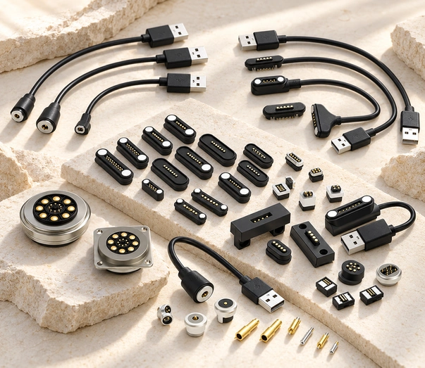
Magtor develops magnetic contact assemblies for guided attachment and stable docking. Designs targeting up to 30A or IP67 protection require model-specific electrical, thermal and sealing validation; magnetic retention does not prevent every disconnection.

17+
Years of manufacturing experience
Magnetic Contact Systems
Founded in 2008, Magtor operates approximately 12,000m² of manufacturing space and employs 185 people, including an R&D team of 12. Our experience covers magnetic contacts and cables, higher-current configurations and sealing designs for the required exposure conditions.
Manufacturing Support
Production equipment and agreed inspections support the required quality controls; acceptance depends on the product specification and results.
Solution Development
The initial engineering response target is within 48 hours after receiving a complete live project brief. Development scope and timing depend on the requirements; a test request does not trigger this service.
Product Categories
Magnetic Connector Configurations
Compare compact, higher-current and sealed configurations with the required contact allocation. Magnetic guidance and locating features can assist mating; error prevention, retention and environmental protection require verification for the selected assembly.
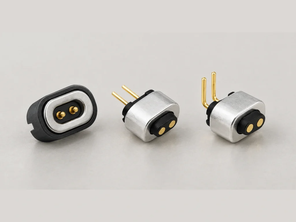
Two-contact Magnetic Connector
A possible interface for small devices such as smart watches and AI glasses, subject to the actual power paths and package requirements.
Two-contact Magnetic Connector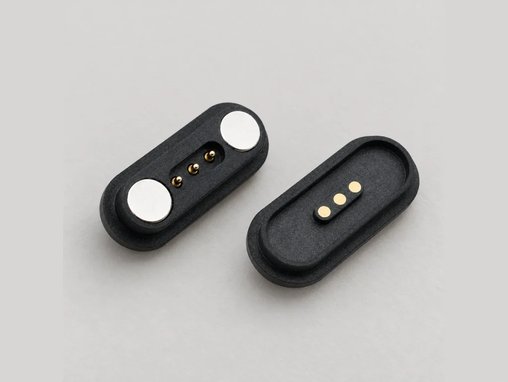
Three-contact Magnetic Connector
Standard arrangements and custom development can be assessed for the required power and supported signal paths.
Three-contact Magnetic Connector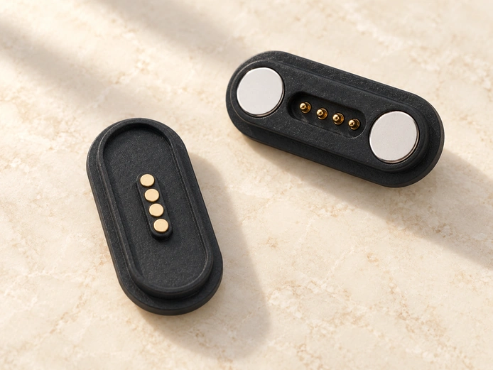
Four-contact Magnetic Connector
A candidate for consumer devices requiring four assigned paths, with a custom sealing design where the exposure requires it.
Four-contact Magnetic Connector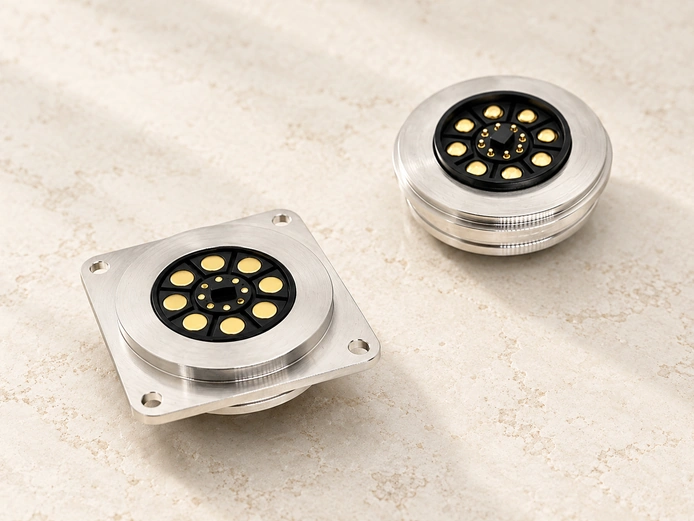
Higher-current Magnetic Connector
A 30A target can be evaluated for equipment such as drones or robots under defined duty-cycle and thermal conditions; it is not a universal continuous rating.
Higher-current Magnetic ConnectorCustom Water-protection Designs
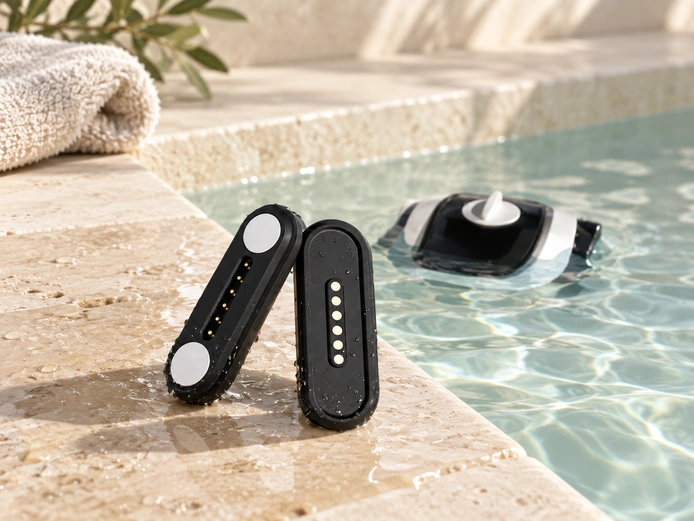
Sealing configurations can be assessed against IP65–IP67 dust and water tests in a defined assembly state. Water protection alone does not establish corrosion resistance, safe charging when wet or unchanged performance after every immersion. Marine, medical and outdoor industrial applications need their own exposure and product-safety qualification.
O-ring and Insert-molding Integration
Contact Finishes for the Exposure
Discuss a Sealing Design
Current Capacity and Magnetic Retention
A design targeting up to 30A may use N52 neodymium magnets and conductive copper-alloy contacts. The complete current path, duty cycle, temperature limits, contact pressure and locating geometry must be checked. Magnetic attraction and housing features can assist mating without guaranteeing an error-proof connection.
30A
Maximum current target, subject to the selected model and conditions
N52
Example neodymium magnet grade
10k+
Example mating-cycle target requiring validation
2.0kgf
Retention-force reference, subject to the selected design
17 Years of Connector Manufacturing
Our magnetic-interface development team evaluates the application requirements,

Manufacturing Facility
Our central company information records 185 employees, an R&D team of 12 and approximately 12,000m² of factory area. The technical team supports project evaluation and development.

Production Equipment
Technical staff and production equipment support process consistency. Confirm the acceptance criteria and test results for the required performance instead of assuming superiority from equipment alone.
Inspection and Testing
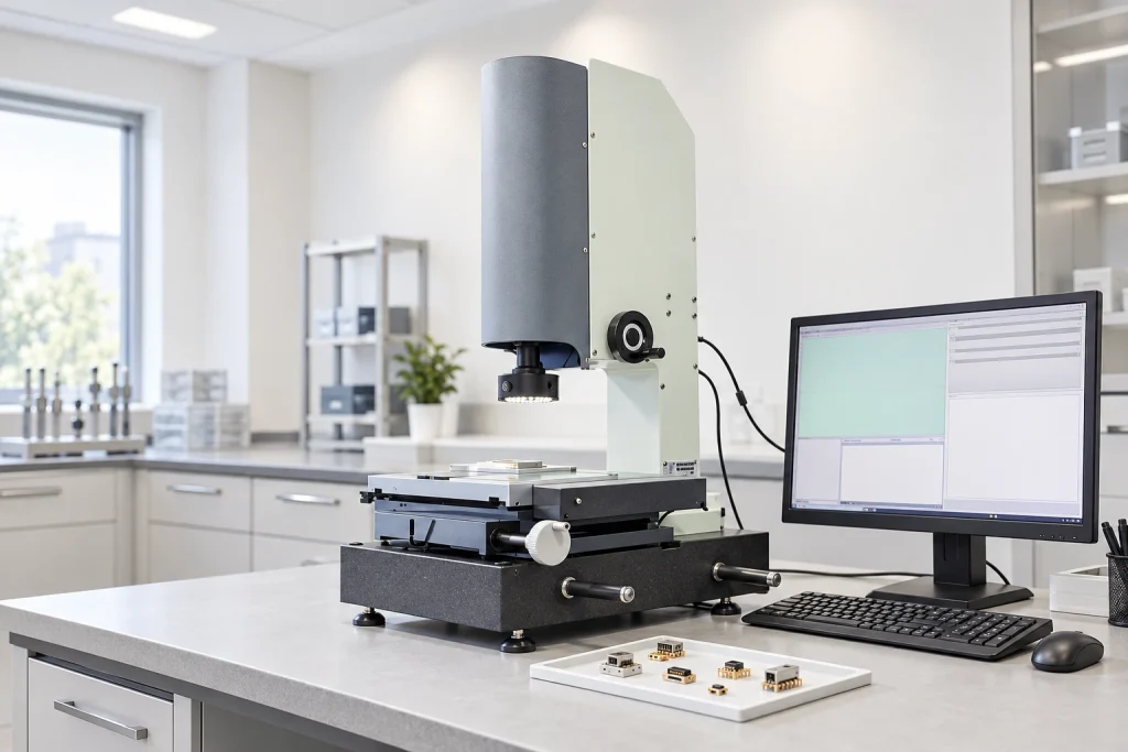
The agreed plan may include mating life, plating thickness, spring-force characteristics, applicable RoHS material checks and CCD inspection. Methods and sampling depend on the product; not every connector undergoes every destructive test.
Engineering Review
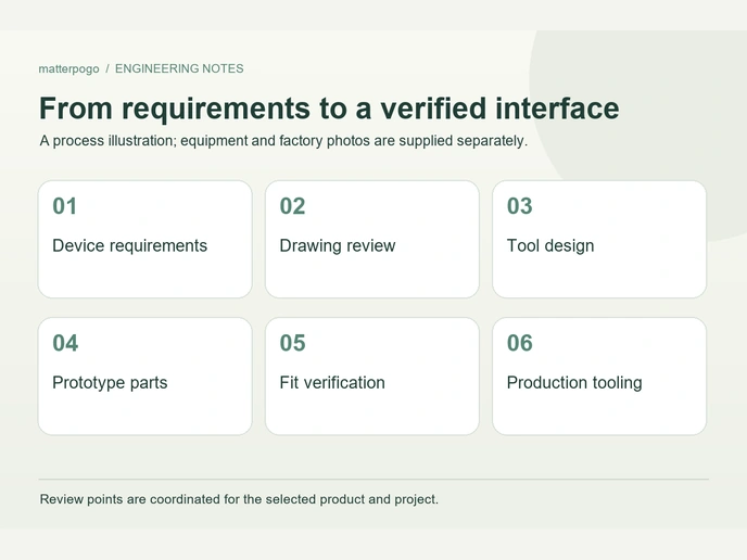
Engineers review the proposed contact system against the application. Confirm the assigned team and validation plan; this does not establish a larger R&D head count than the central company record.

Production Planning
17 years of manufacturing experience support solution development and volume-production planning, with technical assistance and response schedules agreed for the project.
Planning Your Next Interface?
Share your custom contact requirements with Magtor so the electrical, mechanical and manufacturing work can be assessed together.
Long-term Customer Relationships
Working with Enterprise Customers









1 / 10
Management Systems and Documents
Current documents for the new entity are required for the listed manufacturing-management systems.
Technical Questions
Can the Magnetic Interface Be Customized?
With 17 years of manufacturing experience, Magtor can assess contact count, retention, housing geometry and required IP conditions. Solution development, prototypes and tooling should be matched to the actual project rather than described as a guaranteed perfect fit.
What Lead Times Should Be Discussed?
Planning examples are 7–14 days for standard models, about 2–3 weeks for custom prototypes requiring new tooling, followed by around 3–4 weeks for production depending on quantity. Availability, approval and the current schedule must be confirmed in the project quotation; these examples are not guaranteed delivery dates.
Are Evaluation Samples Available?
Samples can be discussed for testing fit and performance before a volume order. For available stock, shipment within 48 hours after payment is a service target to confirm. A custom design may need prototype work first; a development test neither places an order nor initiates payment or shipment.
What Manufacturing Support Does Magtor Offer?
Our experience of more than a decade includes evaluating 30A current targets and IP67 sealing targets for appropriate assemblies. Candidate uses include consumer electronics, wearables, smart-home devices, medical equipment, industrial automation, robotics, drones and other electronic products. Customer relationships and manufacturing experience do not replace model- and device-specific qualification.
Understanding a Magnetic Connector
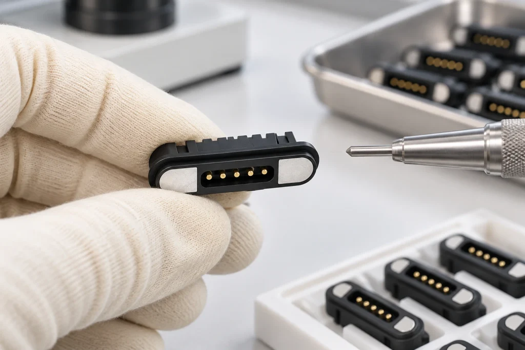
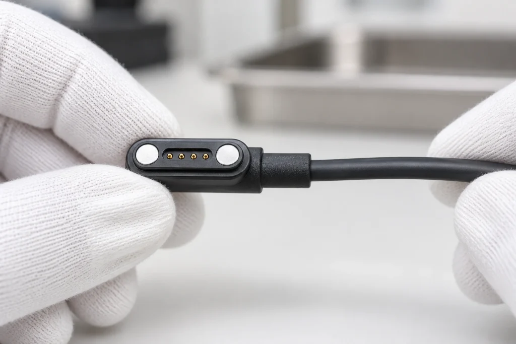
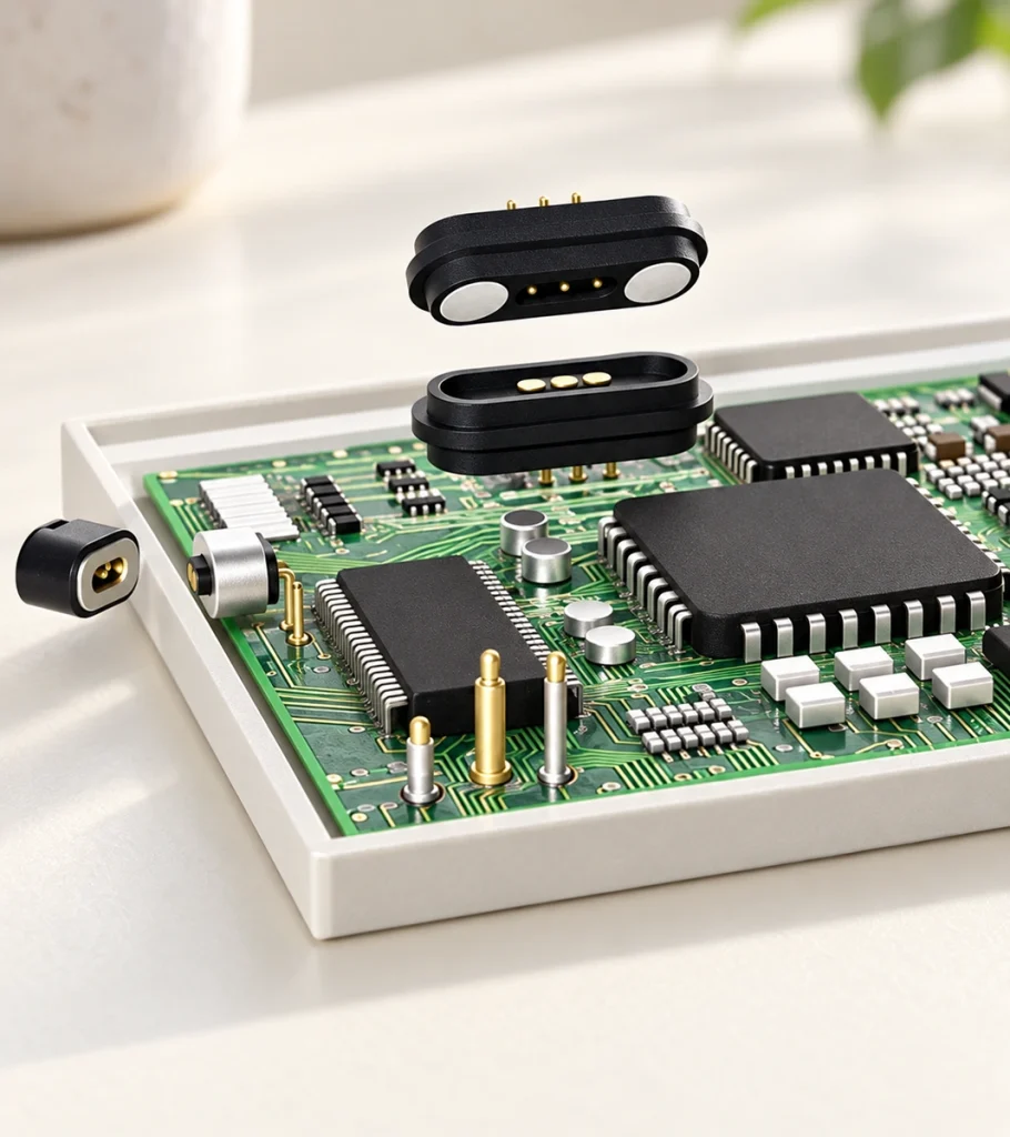
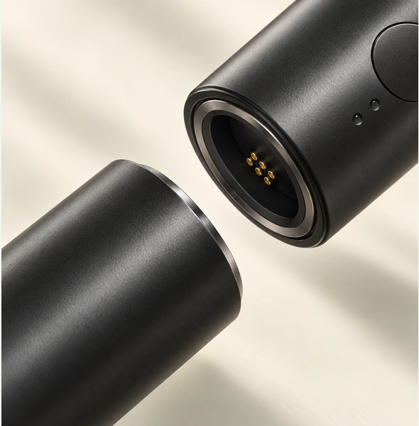
A magnetic contact assembly uses magnets and mechanical locating features to guide mating, while conductive paths carry power or supported signals. A common structure combines spring contacts, a plastic housing and magnets. Attraction, repulsion and housing geometry need to be considered together for the intended orientation.
How Should Retention Force Be Defined?
Required retention depends on the device dimensions, magnet arrangement, total opposing spring force and expected cable or external loads. Comparing only one pin’s spring force is insufficient for a multi-contact assembly. Magnet size, gap and geometry affect the available force, so check the complete system and the intended removal force rather than assume these variables always rise or fall together.
How Does the Contact Finish Affect Performance?
Contact plating affects cost, wear and corrosion behavior. Gold is one possible finish, while a suitable multilayer or composite coating may be considered for a specific exposure. Define thickness, substrate, contact pressure and life testing for the selected assembly instead of assuming a coating improves every performance measure.
Manufacturing a Magnetic Contact Assembly
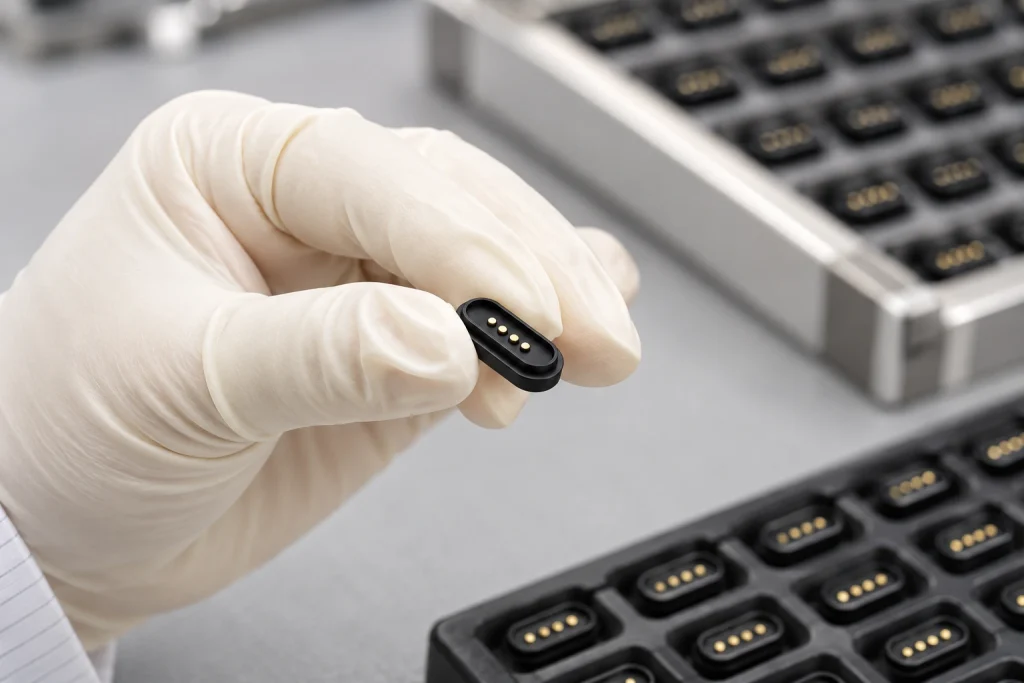
Magtor can plan the process from initial design to the finished assembly. Human inspection and instruments may both support quality controls; the actual checks, sampling and acceptance criteria must be agreed for the product rather than treated as proof that every unit has passed every test.
Incoming-material Inspection
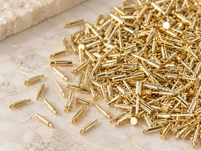
Spring-contact Plating
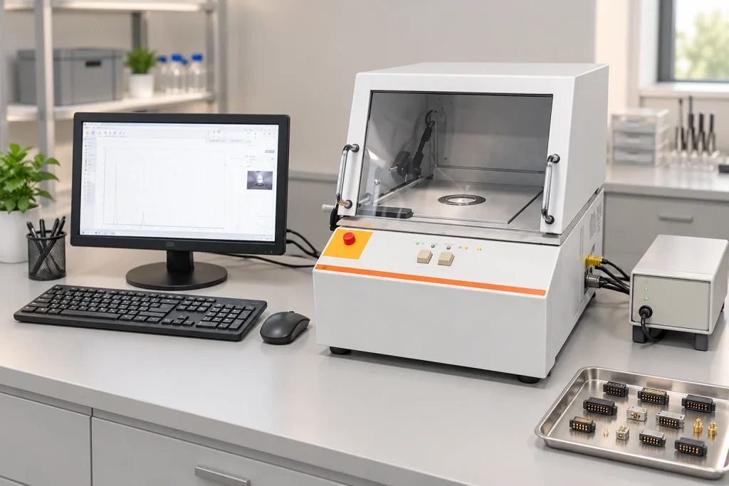
Coating Inspection
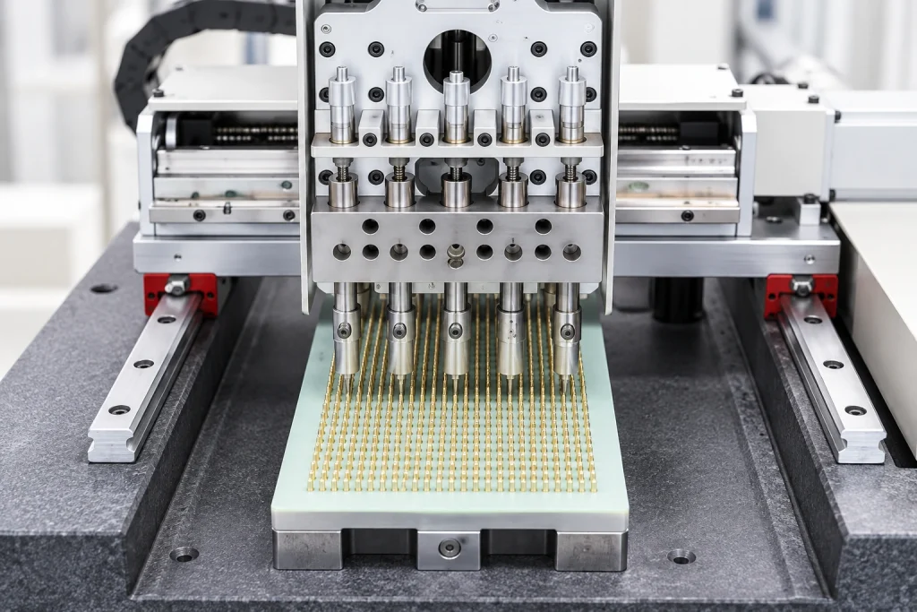
Automated Riveting
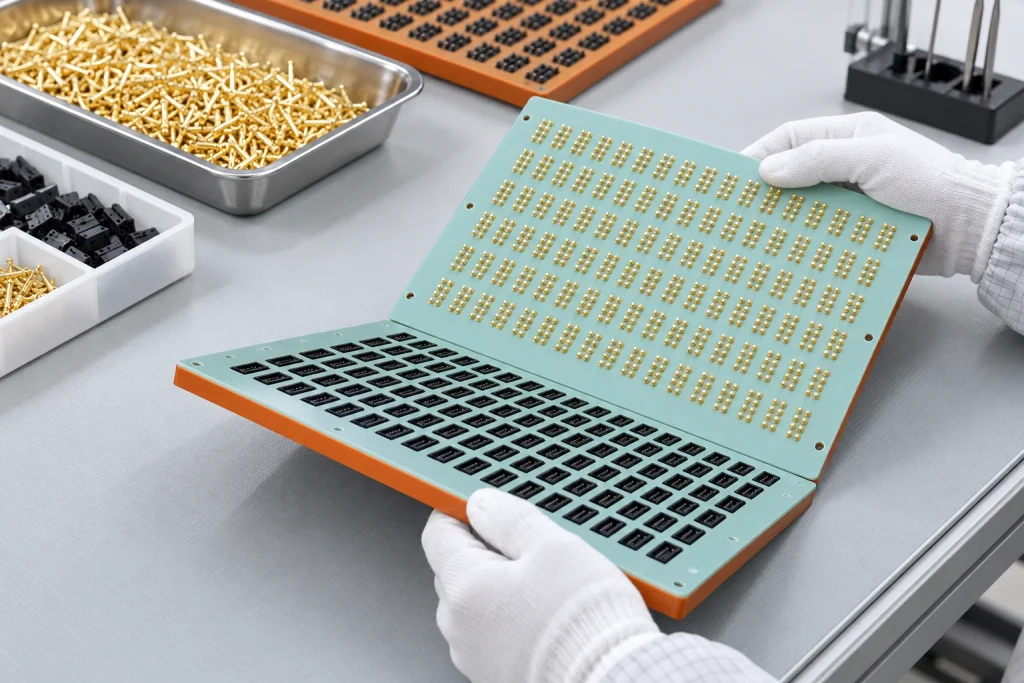
Final Assembly
Quality Inspection

Product Packaging

Shipment
Potential Benefits of Magnetic Interfaces
Magnetic and mechanical design can offer useful attachment, release and packaging characteristics. Evaluate each benefit against the intended device rather than treating it as an automatic property of every contact assembly.
Magnetic Guidance and Retention
Pole placement, attraction or repulsion can assist orientation within the designed capture range. Locating features must establish the final contact position.
Incorrect-mating Protection
Housing geometry and polarity can discourage an incorrect approach. Test reversed and offset cases; the arrangement does not virtually eliminate every possible misalignment without validation.
Mating-life Potential
Tens of thousands of mating cycles, or hundreds of thousands for some specialized designs, are possible test targets. Pressure, sliding, contamination and side loads still cause wear, so verify the selected model under defined conditions.
Controlled Release
A designed release force may allow the contact halves to separate under a pull. Verify the resulting electrical and mechanical behavior in the device; it does not automatically prevent a fall, damage or every safety hazard.
Custom Contact Arrangements
Layouts from one contact to multiple contacts can be assessed against the device’s structure and electrical functions. A complete power circuit still needs an appropriate return path, and compact or higher-current designs require the corresponding spacing and thermal verification.
Request a Technical Quotation
Share the application requirements with our team. 17 years of manufacturing experience support the review of custom development, prototypes and production needs.
Contact details to be supplied
Phone / WhatsApp
Contact details to be supplied
Office and Manufacturing Facility
406, Building 3, No. 12, Zhenyuan Road, Wusha, Chang'an Town, Dongguan City, Guangdong Province, China