
Magnetic Pogo-pin Connectors vs USB: Choosing the Interface
Published on May 22, 2026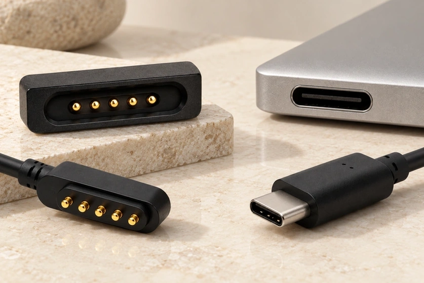
- Understanding a Magnetic Pogo-pin Interface
- Understanding USB Connectors
- Comparing Magnetic Pogo Contacts with USB
- How the Two Interfaces Mate
- Choosing for the Product Requirements
- Questions About Power, Data and Durability
Magnetic pogo contacts provide guided mating and can be customized for a particular enclosure. Their tooling may be economical for a custom project. USB provides standardized connector and protocol options, but supported power and data depend on the complete implementation. Compare development cost, compatibility and the device requirements rather than assuming one interface is always better.
Understanding a Magnetic Pogo-pin Interface
A magnetic pogo-pin interface is designed for convenient, quick mating. Magnets guide and retain the joint while spring contacts make the electrical path. Portable electronics and wearables can benefit from the compact structure and repeated-docking capability when the assembly is specified for the required life.
Magnetic Pogo Contacts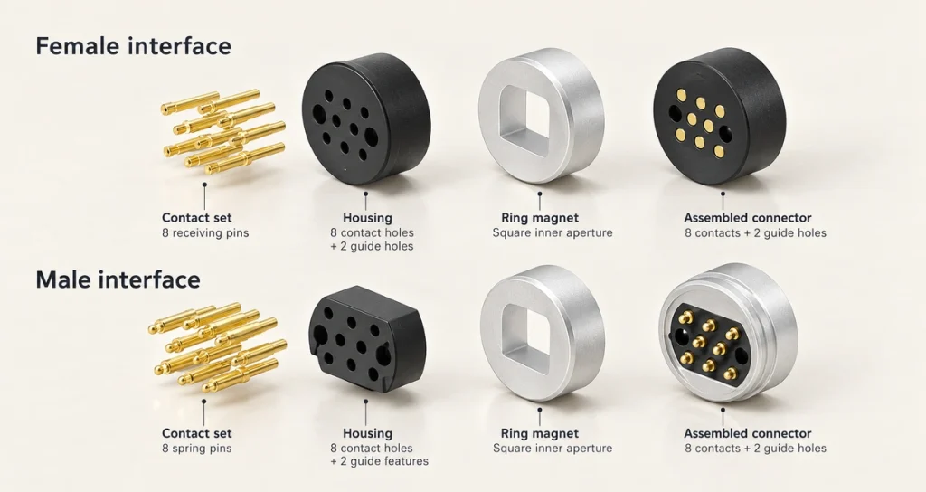
Principle — magnetic alignment and holding force support contact engagement; the electrical contact system determines conduction.
Construction — polarity protection and housing geometry can be incorporated into a design customized for the device.
Examples — wearables, smart home products, industrial equipment, drones, robots, medical equipment and compact electronics.
Potential advantages — a specified long mating life and customizable pin count, appearance and magnetic force. Tooling time and cost are evaluated for the actual project.
Limitations — lateral docking loads can shorten contact life; excessive compression can damage a pin barrel or spring, and fine debris can obstruct the mechanism. These loads and contamination risks need to be addressed in the design.
Understanding USB Connectors
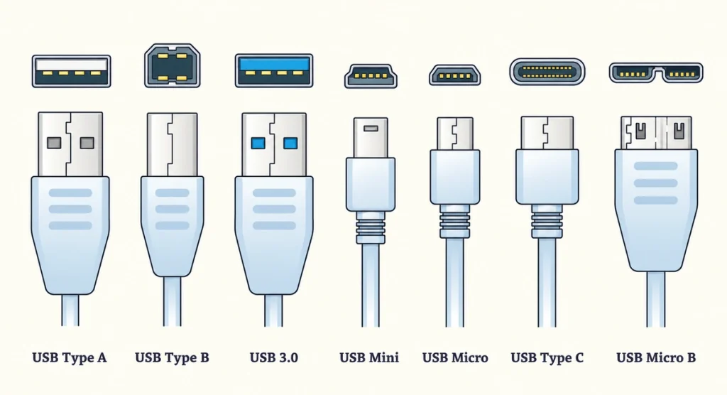
USB provides widely adopted physical interfaces for data and power. USB-A, USB-C and Micro-USB are familiar connector forms used with computers, phones and peripherals. The form factor alone does not guarantee a data rate or power mode: both devices and the cable must support the functions required for the connection.
Principle — Universal Serial Bus protocols define supported data and power functions, according to the implemented specifications.
Universal Serial Bus (USB)Construction — USB connectors use a standardized contact layout and typically a metal shell. IP68 protection requires a specifically sealed assembly and verification of its operating state; a standard USB housing does not provide that protection automatically.
Examples — computers, phones, printers, tablets, external storage and other electronic peripherals.
Advantages — standardized interfaces support broad interoperability across products when their connector, cable and protocol capabilities are compatible. Check the supported power and data functions instead of assuming that every USB connection provides the same performance.
Limitations — standardized dimensions and appearance can be restrictive in a very small device or an enclosure with an unusual geometry.
Comparing Magnetic Pogo Contacts with USB
| Comparison | Magnetic pogo-pin interface | USB interface |
|---|---|---|
| Mating method | Magnetic guidance and contact engagement | Physical plug insertion |
| Current capacity | 1A–30A in the discussed range of custom designs; verify the chosen assembly | Depends on the USB power mode and cable rating; a 5A USB-C/PD configuration needs the appropriate supported cable and devices |
| Data capability | Possible with a contact layout and system designed for the intended signal | Depends on the implemented USB protocol and cable |
| Resistance to wear | Can be suitable for frequent surface mating | Insertion loads and misuse can damage a port; durability depends on the connector family |
| Mating life | 10,000 to 1,000,000 cycles (design-dependent and requiring test evidence) | Illustrative 5,000 to 20,000 cycles; use the selected family and model’s specified durability |
| Water protection | IP67 only for the relevant sealed, verified assembly | IP68 only for a specially sealed and verified assembly |
| Compatibility | A custom interface normally requires a matched mating system | Standardization supports cross-brand use when supported functions match |
| Ecosystem | Generally a dedicated or custom arrangement | A broadly shared standardized ecosystem |
Scroll horizontally to view every column.
Selection note: frequent docking, unusual geometry or a demanding environment may favor a properly designed magnetic pogo interface. Standardized data transfer and broad interoperability may favor USB. Select the complete connection for the product requirements and validation results.
MagtorHow the Two Interfaces Mate
Magnetic Pogo Contacts
Combine spring-loaded contacts with magnetic alignment.
Magnetic capture brings the halves into position.
Reduce the need for precise manual insertion.
Suit blind mating or quick docking when designed for those loads.
USB Plug Hardware
Uses a mechanical plug-and-receptacle arrangement.
Requires the appropriate mating orientation; USB-C is reversible, while other forms have their specified orientation.
Uses mechanical retention rather than magnetic alignment.
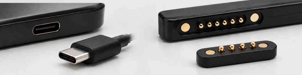
The distinction is the mating mechanism: magnetic pogo interfaces combine electrical surface contact with magnetic guidance, while a USB plug uses mechanical insertion. Both still need a correctly implemented electrical system.
Choosing for the Product Requirements
Evaluate the operating environment, power demand, available space, required life and user handling. These considerations apply whether the product is a wearable, medical device, smart home product or industrial system.
USB is attractive where standardized high-speed data and interoperability are important, subject to the supported protocol and cable. Magnetic spring contacts provide more freedom in compact geometry, guided docking and custom pin or current arrangements, with cycle life verified for the specific design.
Questions About Power, Data and Durability
Can a Magnetic Pogo Interface Carry Data?
Yes, when the contact arrangement and electronics are designed for data. USB 2.0 is one implementation option; it is not a universal limit established by magnetic mating itself. A standard USB interface may be preferable when the product requires a specified higher-speed USB mode and broad compatibility.
What Current Range Can a Magnetic Pogo Design Support?
The discussed custom design range is 1 A to 30 A. Verify the actual connector rating, contacts, thermal conditions and operating load rather than applying that range to every pogo interface.
How Should Mating Life Be Compared?
Surface mating can reduce sliding wear, but it does not establish a fixed multiple of USB life. Compare the specified mating-cycle tests and contact performance of the particular magnetic and USB assemblies.
Does USB Work with Every Device?
USB is widely adopted, but not every device has the same connector form or supports the same functions. Some combinations need an appropriate adapter or cable and compatible protocols.
Is a Magnetic Interface Always Better Than USB?
Neither interface is better for every product. Compare their benefits and limitations with the device’s power, data, space, life and handling requirements.