
Male and Female Magnetic Connectors: Understanding the Contact Structures
Published on June 11, 2026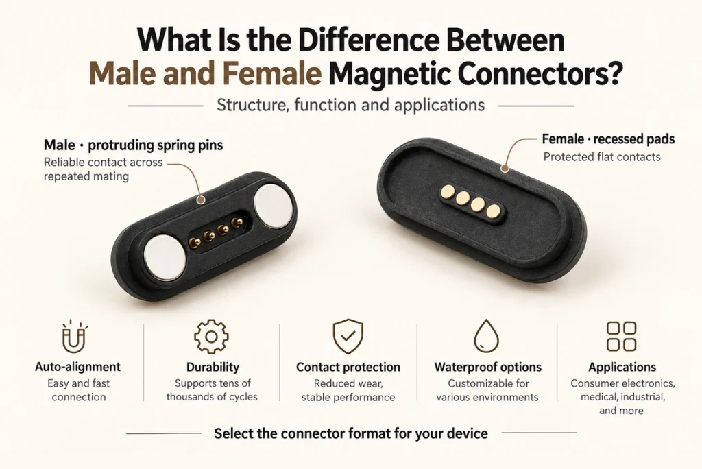
- Basic Functions of a Magnetic Interface
- The Spring-contact Half
- The Fixed-contact Half
- Comparing the Two Contact Structures
- Magnetic Alignment in Operation
- Where the Pogo Contacts Are Placed
- Selection Requirements
- A Common Cable-to-device Arrangement
- Requirements for a Custom Design
Magnetic interfaces may be used in consumer electronics, medical equipment and industrial products. Understanding the two mating contact structures helps engineers choose their placement and integration method. This guide describes the spring-loaded and fixed-contact arrangements commonly called male and female, while recognizing that the naming and placement can vary between designs.
Basic Functions of a Magnetic Interface
Two mating assemblies use magnets to guide and retain their conductive contacts. The interface may implement the following functions when the contact allocation and system design support them:
magnetic connectorPower transfer only.
Data transfer only.
Power and supported data together.
Other signal communication.
High-current charging through a suitable rated assembly.
The electrical paths may use spring-loaded pogo contacts, flat contact surfaces or custom terminals. Their design and mating pressure determine performance over repeated connections.
The Spring-contact Half
In the arrangement described here, the male half has projecting contacts that compress under load. A pogo contact typically includes a plunger, barrel, spring and the required insulating structure. Compression through the specified working travel establishes the intended contact force.
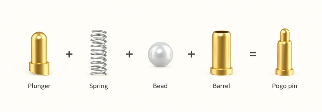
Typical characteristics of this structure are:
A plunger that moves through its working travel.
An internal spring.
An exposed moving-contact design that is not inherently sealed.
Spring return after compression.
An arrangement that can be integrated into a cable head or dock.
Potential Advantages of Spring Contacts
1. Contact Pressure
Spring compliance can accommodate the specified alignment and height tolerances while maintaining electrical contact pressure. Validate resistance and engagement at the actual tolerance limits.
2. Accommodation of Movement
Within their permitted travel and load limits, pogo contacts can accommodate small movement, vibration and manufacturing differences.
3. Repeated-mating Capability
Suitable spring-contact designs may target tens of thousands or hundreds of thousands of cycles. Those examples do not establish zero degradation: confirm allowable wear and resistance change through tests of the chosen contact and operating conditions.
4. Assembly Access
An accessible pin arrangement may simplify parts of manufacturing and assembly, depending on the mounting process and fixture design.
The Fixed-contact Half
The matching half described as female uses fixed copper contacts installed at or within the device surface. The mating faces may be flat or slightly recessed to meet the spring contacts. Their exact geometry and insulation need to follow the assembly drawing.
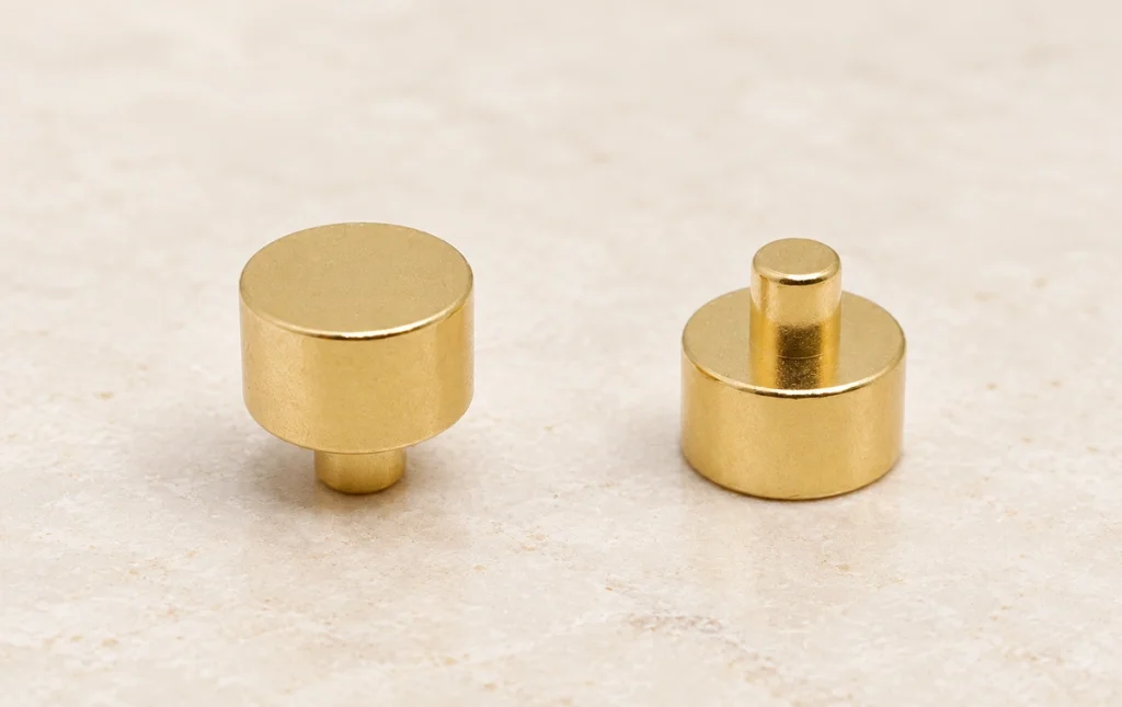
Typical features include:
Flat mating faces.
A slightly recessed contact option.
Corrosion performance specified for the real exposure.
Potential Advantages of Fixed Contacts
1. Located Mating Surfaces
A suitable recess can help locate the spring-contact tip and protect parts of the contact face, depending on the mating geometry.
2. Flush Device Integration
Fixed contacts can be integrated near flush with the enclosure, leaving the intended mating face accessible while limiting changes to the product’s appearance and feel.
3. Sealing Options
A fixed-contact half may include a sealing structure targeting IP67. Verify the relevant device-side assembly, protected area and test state; that rating does not automatically extend to the spring-contact half or to every cleaning condition.
4. Reduced Moving-part Wear
A fixed structure has fewer moving parts than a pogo contact, but its mating face can still wear or corrode. Its service life depends on materials, contact loading, exposure and the selected design’s validation.
Comparing the Two Contact Structures
| Feature | Spring-contact half (male in this example) | Fixed-contact half (female in this example) |
|---|---|---|
| Principal parts | Plungers, barrels and springs | Fixed copper contacts |
| Movement | Compresses and returns through the specified travel | Fixed mating surface |
| Water protection | The exposed moving-contact structure described here is unsealed | A suitable device-side sealing design may target IP65–IP67 |
| Corrosion requirements | Set by the actual application | Set by the actual application |
| Cleaning access | Moving parts require a compatible method | A fixed face may be easier to clean |
| Common installation example | Cable side | Device side |
Scroll horizontally to view every column.
Magnetic Alignment in Operation
Permanent magnets guide the mating faces toward their intended position, while the locating structure controls the final contact alignment. This avoids relying entirely on insertion into a conventional socket.
During engagement of the two halves:
Magnetic attraction guides the approach.
The mating faces locate in the intended position.
Corresponding contacts establish their electrical paths.
The magnetic arrangement retains the seated assembly.
A well-designed arrangement can simplify attachment and reduce some mis-mating and insertion-related wear. Verify those benefits against the actual approach angles, tolerances and operating loads.
Where the Pogo Contacts Are Placed
The terminology used in this example is:
Male half — the spring-loaded pogo contacts.
Female half — the fixed copper contacts.
That convention does not apply universally to every magnetic connector.
A custom design may put spring contacts on the device and fixed mating surfaces on the cable instead. The appropriate placement follows requirements such as:
Electrical and user safety.
The sealing arrangement.
Available product space.
Current rating and thermal behavior.
Manufacturing and assembly needs.
Selection Requirements
Review the complete magnetic interface against the following groups of requirements.
Electrical Requirements
Specify:
The required current and rating conditions.
Operating voltage and insulation requirements.
Signal functions.
Required data rate and supported protocol.
Allowable contact resistance.
Operating Environment
Define:
Water-protection requirements.
Dust exposure.
Corrosion conditions.
Vibration loads.
Operating temperature range.
Mechanical Life and Loads
Determine:
How frequently the product will mate.
The intended service life.
Holding and release force.
Impact requirements.
User Handling
Convenient operation is a common reason to consider a magnetic interface. Review whether the product provides:
Straightforward blind mating.
A stable seated connection.
A comfortable release force.
Validated performance during the expected use.
A Common Cable-to-device Arrangement
Spring Contacts on the Cable; Fixed Contacts on the Device
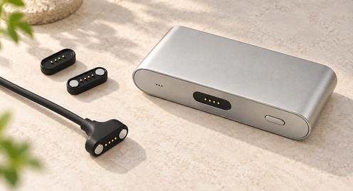
This is a common arrangement to consider, rather than a required layout for every electronic device.
Potential integration benefits include:
Protection of the device-side structure.
A layout that limits unnecessary exposure of projecting contacts.
A relatively flush device appearance.
A simple docking arrangement.
Accessible maintenance of the fixed face.
Quick automated engagement where alignment is suitably controlled.
Application examples include:
Smartwatches.
Earbuds.
Medical devices.
Consumer electronics.
Robots.
Industrial equipment.
Shared-use devices.
Charging stations.
A device-side fixed contact and cable- or dock-side pogo contact is one useful configuration. Specialized equipment may reverse that placement or use another structure, so follow the requirements and drawings of the actual interface.
Requirements for a Custom Design
For a custom interface, define the following inputs together:
Contact count, with 2–20+ contacts as an illustrative design range.
Required current capacity.
Magnetic holding and release force.
The specified IP protection and assembly state.
Contact-coating system.
Housing material.
Permitted connector dimensions.
Orientation and reverse-mating control.
Custom structures may serve compact wearables or higher-current industrial equipment when the proposed geometry, materials and electrical paths satisfy the application and validation plan.
Conclusion
The spring-contact half is mechanically more complex than a fixed-contact face. Together they can provide quick mating and stable electrical paths when their geometry, force and materials are properly specified. Confirm which side contains each structure and how the supplier names it; male and female labels alone do not establish pin placement, sealing or reliability.