
Magnetic Power Connectors: Design, Demonstrations and Production Planning
Published on August 13, 2026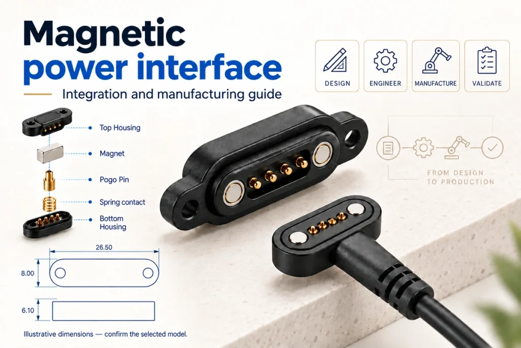
- Magnetic retention and the conductive path
- Developing the mating pair
- Magnetising a steel pin: a different task
- A temporary electromagnet demonstration
- The charging circuit and magnetic interface
- Quoting a custom power connector
- Production quantity and schedule
A magnetic power interface brings spring contacts, matching pads, magnets, polarity keying, insulation and suitable conductors into a mating pair. Keep magnetic retention separate from the current path, then assess resistance, heating, forces and fault protection. This guide distinguishes a prototype demonstration from a production-ready connector.
spring contactsneodymium magnetscontact resistancefault protectionVideo material pending replacement
Magnetic retention and the conductive path
Magnets position and retain the halves; contacts and pads carry current. Depending on the design, the conductive path may use plated spring contacts, copper-alloy terminals or stamped contacts. Select each part for its role rather than using a magnet as an exposed live conductor.
magnetic power interfaceA low-voltage DC interface can include:
| Component | Purpose | Engineering Notes |
|---|---|---|
| Pogo pins or spring contacts | Carry power and signal | Select by current rating, stroke, plating, and lifecycle |
| Contact pads | Mating surface | Specify a suitable gold or other corrosion-resistant contact finish |
| Neodymium magnets | Alignment and holding force | Keep magnets isolated from live conductors |
| Plastic housing | Insulation and mechanical structure | PA, PBT, PC, or custom molded material |
| Polarity keying | Limits reversed engagement when the keying is validated | Use asymmetric shape, magnet polarity, or pin layout |
| Fuse/PTC protection | Fault protection | Select fault protection for the charging or battery circuit; a fuse or PTC alone may not provide every required function |
| Strain relief | Cable protection | Limits repeated wire strain near the housing |
Scroll horizontally to view every column.
A development outline is:
Define voltage, continuous and peak current, pin functions, conductor size and environment.
Choose contacts with suitable current limits, working travel and force.
Arrange the magnets for the intended guidance and keep them insulated from live conductors.
Use housing and polarity features that prevent incorrect electrical engagement.
Terminate conductors by the specified soldering or crimping process.
Secure or seal the assembly using a validated mechanical, potting or overmoulding process.
Check continuity, polarity, resistance, temperature rise and the relevant mating and release forces.
Design note: Review polarity keying, contact size and clearance between magnets and conductors early. Magnetic retention and electrical conduction have separate requirements; a convenient snap action does not establish a safe or durable current path.
Developing the mating pair
Develop both halves together, with compatible spring contacts or pads, magnet polarity and mechanical guides. Define the permitted alignment range and working compression, prevent reversed engagement, and specify materials for voltage, current, temperature and life requirements.
Video material pending replacement
Five design-review steps
Application: Define whether the interface serves charging, LED lighting, batteries, sensors, medical equipment or industrial use, with the relevant product requirements.
magnetic interfaceContacts: Select a compliant contact system for the required current and working travel; limited axial compliance does not replace mechanical alignment.
Magnets: Use attraction for guidance and retention, keeping the magnets outside the live current path.
Keying: Assess housing, polarity and contact layout so reversed engagement cannot create the wrong electrical connection.
Electrical validation: Evaluate arcing, shorts, heating and contact with stray metal under the intended operating conditions.
| Design Choice | DIY Connector | Production Magnetic Connector |
|---|---|---|
| Contacts | Hand-soldered pins | Custom pogo pins or stamped terminals |
| Housing | 3D printed or glued | Injection molded or overmolded |
| Reliability | Prototype level | Requires model-specific life testing and acceptance criteria |
| Waterproofing | Protection limited to the demonstrated prototype conditions | An IP target is possible with complete-assembly qualification |
| Cost control | Suitable for evaluating a small prototype build | Process and tooling costs can be spread over production volume |
Scroll horizontally to view every column.
Design note: Strong attraction can coexist with poor electrical contact. Coordinate spring force, plating, working height and actual release effort, then measure resistance and heating in the proposed assembly.
Magnetising a steel pin: a different task
A ferromagnetic steel pin may acquire weak magnetism through repeated one-direction strokes with a permanent magnet. A current-controlled coil can instead produce temporary magnetism. Neither method supplies the conductivity, plating or spring performance required of a connector contact.
Magnetic material versus contact material
Iron and some steel grades are ferromagnetic. Many contacts use brass, phosphor bronze, beryllium copper or another copper alloy for conductivity and mechanical behaviour. Assess the actual alloy, heat treatment and finish; the word “pin” does not establish whether it can be magnetised.
ferromagnetic material| Pin Material | Can It Be Magnetized? | Good for Electrical Contacts? |
|---|---|---|
| Mild steel | Yes | Assess its conductivity and corrosion protection for the application |
| Stainless steel | Sometimes, depends on grade | Depends on grade and contact requirements |
| Brass | Not normally; confirm the alloy and finish | Good for some terminals |
| Phosphor bronze | Not normally; confirm the alloy and finish | Good spring contact material |
| Beryllium copper | No | Can suit spring contacts with an appropriate grade and process |
| Copper alloy with gold plating | Depends on the underlying alloy and plating layers | Can suit low-resistance contacts with a specified finish |
Scroll horizontally to view every column.
For a simple steel-pin demonstration:
Check that the pin responds to a magnet; attraction alone does not identify its exact alloy.
Stroke it in one direction with a permanent magnet.
The illustrative method repeats 50–100 strokes without reversing; this is not a calibrated magnetic-strength specification.
Check for attraction of small steel pieces without treating that as a connector qualification.
Expect weak magnetisation that may diminish; it is not an industrial permanent-magnet substitute.
Design note: Choose conductors for electrical and environmental requirements and choose magnets for retention. Magnetic steel is not automatically a suitable power contact; compare the actual material, finish, resistance and exposure.
A temporary electromagnet demonstration
A coil around an iron core develops a magnetic field when a suitable controlled DC current flows. Turns, current and core material influence the result. A demonstration needs current limiting, insulation and temperature monitoring; directly connecting an unspecified coil to a battery is not a controlled power design.
temporary electromagnetTemporary electromagnet principle
A simple coil loses its field when its current stops. Manufacturing a neodymium permanent magnet is a different industrial process involving specified materials and processing, rather than an equivalent home-built coil.
| Method | Magnet Type | Demonstration or reuse scope | Notes |
|---|---|---|---|
| Wire around iron nail | Electromagnet | Only with a suitably controlled low-voltage supply | Current, insulation and temperature need control |
| Salvaged speaker magnet | Permanent magnet | Reuse of an existing manufactured part | Already manufactured |
| Magnetizing steel with magnet | Weak permanent magnet | Weak demonstration magnetisation | No guaranteed strength or long-term retention |
| Making neodymium magnet | Permanent magnet | No | Requires industrial process |
Scroll horizontally to view every column.
A controlled demonstration outline is:
Choose a suitable iron core for the demonstration.
Wind insulated copper wire without damaging its insulation.
Expose only the ends needed for the connections.
Use a current-limited low-voltage DC supply with defined current and temperature limits.
Monitor temperature and stop before exceeding those limits; touch is not the sole protective measure.
Do not connect the coil directly to mains or an unprotected battery.
For a connector, use specified magnet grades from a traceable supplier. Agree the required material and inspection evidence rather than assuming an unspecified “certified” magnet meets the design.
Design note: Repeatable retention depends on a controlled magnet grade, geometry and assembly. For coils, defined current and thermal protection are essential; short energisation time alone is not adequate protection.
The charging circuit and magnetic interface
Start with a regulated charging circuit matched to the battery and load. Add the magnetic contact interface with its required power and signal paths, then review polarity, current, thermal and short-circuit protection before evaluating a connected device.
Video material pending replacement
Charging-system elements
The detachable contact assembly is one part of a charger. The system must implement the battery’s charging requirements and any relevant USB data or identification functions. A magnetic housing or contact count does not establish USB Power Delivery or device compatibility.
| Charger Element | Function | Critical Requirement |
|---|---|---|
| Power source | Supplies voltage | Must be regulated |
| Charging IC or controller | Manages battery charging | A suitable battery-management and charging function is required for the cell chemistry |
| Magnetic connector | Detachable interface | Control short-circuit and exposed-contact risks in the complete system |
| Pogo pins | Conduct current | Validated for the specified charging current and thermal conditions |
| Magnets | Hold alignment | Electrically isolated |
| Protection circuit | Prevents faults | Assess overvoltage, overcurrent, thermal and polarity protection for the circuit |
Scroll horizontally to view every column.
A development sequence is:
Identify battery chemistry, voltage and its required charging profile.
Choose a suitable charging controller or module with applicable documentation and validation evidence.
Choose contacts for the specified current path and operating conditions.
Assign VBUS, GND and any required data or identification functions from the circuit.
Assess reverse polarity, shorts and the other relevant electrical faults.
Provide mechanical and magnetic keying for correct engagement.
Evaluate the design with a current-limited bench supply and defined checks before device connection.
Video material pending replacement
Design note: One successful charge is insufficient for approval. Check repeated mating, resistance drift, temperature rise and stray-metal shorting risks under defined conditions, with supporting results for the proposed design.
Quoting a custom power connector
Review pin count, current requirement, magnet dimensions, finish, cable, housing, seals, tooling, required compliance work and volume. A target below one dollar in a high-volume simple design is only a pricing illustration, not a quotation. Custom overmoulding or higher-current requirements need their own costed specification.
Cost drivers
Separate the recurring unit price from engineering, tooling and setup charges. Small prototype quantities spread drawing, setup and test costs over fewer parts, so compare the complete scope and quantity basis.
| Cost Driver | Simpler or existing design scope | Additional or customised scope |
|---|---|---|
| Pin count | 2-pin power only | Multi-pin power + signal |
| Current rating | Low-current pogo pins | High-current custom terminals |
| Plating | Finish selected for the actual exposure and life target | Specified thicker finish where the requirements justify it |
| Housing | Standard plastic | Custom molded or waterproof |
| Cable | PVC standard cable | Silicone, shielded, high-flex cable |
| Magnet | Small standard magnet | Custom grade/shape magnet |
| Testing | The inspection and tests required by the agreed specification | Additional reliability qualification where required |
| Volume | Production quantity can reduce unit cost | A small custom run may carry higher setup cost per part |
Scroll horizontally to view every column.
Quotation items can include:
Engineering review and DFM.
Prototype or sample fee.
Mold or tooling fee if custom housing is required.
Unit price based on quantity tiers.
Testing, packaging, and logistics costs.
Design note: Compare landed cost, test coverage, life requirements and failure risk using equivalent specifications. A low unit price does not compensate for unacceptable heat, wear or intermittent contact.
Production quantity and schedule
Minimum quantity and schedule depend on the design changes and supply scope. Existing or partly customised assemblies may avoid some tooling, while a new moulded design needs drawings, samples, validation and a pilot build before production release.
Scope by customisation level
| Project Type | Quantity basis to confirm | Schedule basis to confirm | Best For |
|---|---|---|---|
| Standard magnetic connector | Confirm the supplier’s actual minimum quantity | May avoid new tooling; confirm stock and validation | Early prototypes and small batches |
| Semi-custom cable assembly | Confirm the assembly-specific minimum quantity | Depends on cable, termination and validation scope | Custom length, wire, or pinout |
| Custom housing without tooling change | Confirm feasibility and minimum quantity | Small changes can still require tooling or further validation | Minor appearance or structure changes, if existing tooling permits |
| Fully custom molded connector | Confirm tooling and economic production quantity | Includes new tooling and the agreed validation stages | A production product with a distinct industrial design |
| Waterproof/high-current custom design | Confirm quantity against the required manufacturing process | Includes the specified ingress, current and reliability validation | Industrial, outdoor, medical, or battery systems |
Scroll horizontally to view every column.
A production-review sequence is:
Requirement review: voltage, current, pinout, environment.
Drawing and 3D structure confirmation.
Prototype or sample build.
Electrical and mechanical testing.
Tooling if custom molded parts are needed.
Pilot run for process validation.
Mass production and final QC.
The schedule depends on magnet availability, plating, cable changes, tooling complexity and the agreed test requirements. Confirm those inputs instead of treating relative table labels as a delivery promise.
Design note: Confirm current requirements, cable length, pinout, mating direction and ingress conditions before tooling. Resolving these inputs early reduces the risk of changing the mechanical design later.
MagtorKeep magnetic guidance separate from conduction, then validate the complete interface’s safety requirements, service life and manufacturability before production release.