
Magnetic Pogo Pin, USB-C or Wireless Charging: Choosing for Your Device
Published on September 22, 2026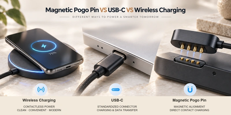
- How the Three Charging Interfaces Work
- Magnetic Pogo Pin, USB-C and Wireless Charging Compared
- Assessing Power and Data Requirements
- Designing for Compact Size and Water Exposure
- Comparing Everyday Charging Use
- Engineering Limitations to Consider
- Selecting an Interface for an OEM Device
These three charging methods deliver energy through different interfaces. Magnetic pogo pins use conductive contacts with magnetic alignment; USB-C combines a standardized connector with power and data functions; wireless charging transfers energy without exposed charging contacts. Choosing between them requires a review of charging power, data needs, product size, water protection, accessory compatibility and the way users will charge the device.
How the Three Charging Interfaces Work
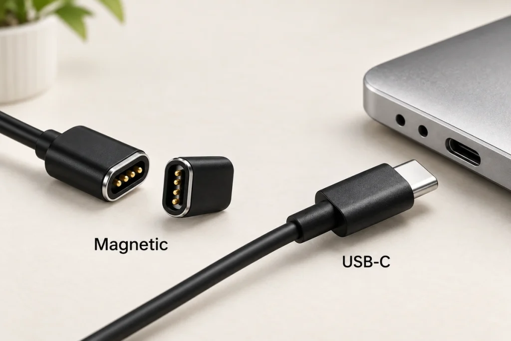
In a magnetic pogo pin connector, the contacts carry the electrical current and the magnets position and hold the mating parts. Engineers can adapt its dimensions, pin count, pitch, magnetic force, cable direction and electrical functions to the product. This approach suits repeated connections in wearables, charging docks, smart glasses, medical devices, handheld equipment and other custom products. The Magtor Magnetic Cable Connector range illustrates how contact layouts can be configured for different power and signal requirements.
pin countMagnetic Cable Connector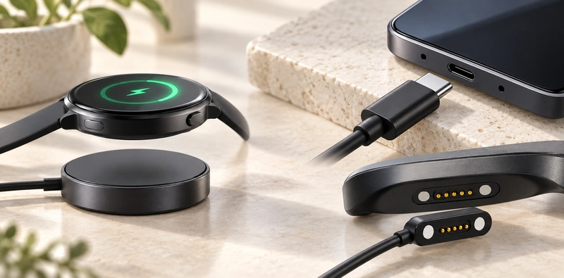
USB-C uses conductive contacts within a standardized connector ecosystem. The USB Type-C specification from USB-IF defines that connector system; the device's implemented USB protocols determine its actual power and data functions. Wireless charging transfers energy by magnetic induction instead of a direct conductive charging connection. Qi2 systems can also use magnetic attachment to improve alignment, as described by the Wireless Power Consortium Qi standard.
USB Type-C specification from USB-IFWireless Power Consortium Qi standardMagnetic Pogo Pin, USB-C and Wireless Charging Compared
| Factor | Magnetic Pogo Pin | USB-C | Wireless Charging |
|---|---|---|---|
| Power transfer | Direct electrical contact | Direct electrical contact | Wireless inductive transfer |
| Alignment | Magnetic | Manual plug insertion | Placement or magnetic alignment |
| Interface design | Highly customizable | Standardized connector | Coil-based system |
| Device opening | External contacts possible | Receptacle required | No charging connector opening |
| Data / signals | Possible with suitable pin design | Major ecosystem advantage | Usually handled separately |
| Breakaway connection | Possible | Normally retained mechanically | No plug connection |
| Exposed charging contacts | Usually yes | Contacts inside receptacle | No |
| Internal space | Custom contact geometry | Standard connector footprint | Coil + electronics required |
| Accessory compatibility | Usually device-specific | Broad ecosystem | Depends on wireless standard |
| Typical fit | Wearables, docks, custom OEM devices | Phones, tablets, laptops, general electronics | Phones, sealed consumer devices |
Scroll horizontally to view every column.
Use this comparison to guide design decisions, rather than to rank measured performance. A magnetic pogo pin interface may be developed for a very small wearable or for an application requiring much higher current. USB-C implementations likewise vary considerably in their supported power and data functions. For wireless charging, coil design, alignment, thermal management and the selected wireless power standard all influence the result.
Assessing Power and Data Requirements
USB-C is useful when the product needs a widely adopted, standardized interface for both power and data. In compatible USB Type-C systems, USB Power Delivery supports up to 240 W when the specification, cable, source and device configuration meet the relevant requirements. The connector shape alone does not establish support for USB PD, USB4 or any particular data speed; each implemented function must be stated separately. The USB-IF USB Power Delivery information describes the power-delivery system.
USB-IF USB Power Delivery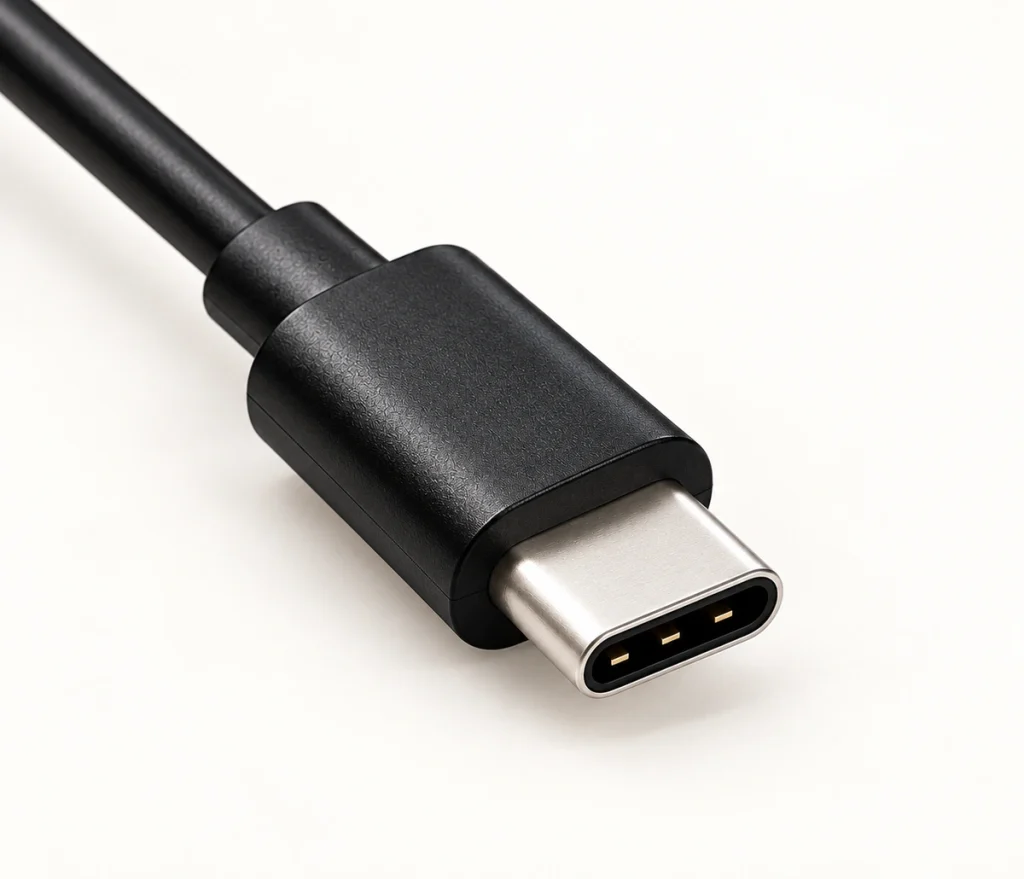
A magnetic pogo pin interface gives designers flexibility to assign contacts around a custom product. Extra paths may carry power, ground, detection, ID, control or signals. A 6 Pin Magnetic Charging Cable or 8 Pin Magnetic Cable Connector therefore offers more electrical paths than a basic two-pin charging interface. Four, six or eight contacts do not, by themselves, establish USB data capability: the pin assignment, cable construction, protocol and signal integrity must support the intended function. Wireless charging primarily transfers power, so devices needing data synchronization usually provide another communication interface.
6 Pin Magnetic Charging Cable8 Pin Magnetic Cable ConnectorDesigning for Compact Size and Water Exposure
For compact equipment, magnetic pogo pin charging can place contact pads on the device exterior, reducing the need for a deep plug-in receptacle. Pin spacing, housing geometry, magnet position and working stroke can be tailored to the available enclosure space. USB-C is a slim, reversible connector developed for mobile products, although its integration still needs the specified receptacle and an enclosure opening. These mechanical requirements are covered by the USB Type-C Cable and Connector Specification.
USB Type-C Cable and Connector Specification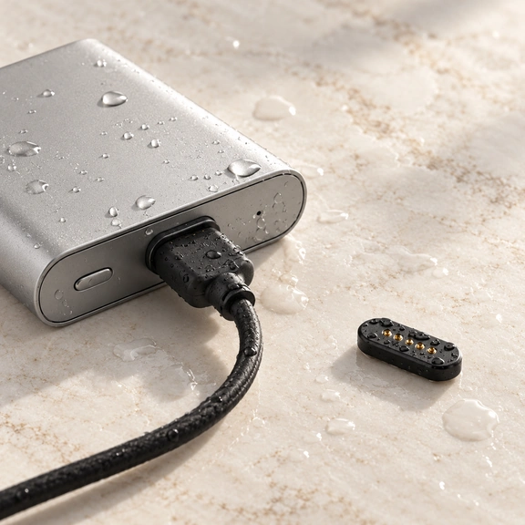
With wireless charging, the product exterior can remain free of exposed charging contacts. A sealed surface may be simpler to design, but the receiver coil, shielding, charging electronics and thermal requirements still take space inside the product. Whichever charging method is used, ingress protection must be assessed for the complete enclosure; the connector type alone does not establish an IP rating. IEC 60529 defines the classifications. Magnetic pogo pin wearables also need exposed contacts designed for moisture and sweat, making contact plating and corrosion resistance important factors in selection.
IEC 60529contact plating and corrosion resistanceComparing Everyday Charging Use
Many users already have compatible USB-C accessories for phones, tablets, laptops and other electronics. Its reversible plug is easier to orient than older directional USB connectors. Magnetic pogo pin charging follows a different connection sequence: bring the connector toward the mating surface, let the magnets guide alignment, and allow the spring contacts to engage. A suitable design can support blind mating, frequent docking and a breakaway connection without repeated plug insertion.
Wireless charging lets the user place a device on a compatible surface without inserting a cable into the device. Newer Qi2 systems add magnetic attachment to align the charger and product. According to the Wireless Power Consortium, Qi2 introduced magnetic attachment with 15 W charging, and Qi2 25W later increased standardized Qi charging power. The WPC Qi wireless charging information explains that development. Evaluate whether users need widely compatible plugs, magnetic docking or placement without charging contacts; that requirement will guide the preferred charging experience.
WPC Qi wireless chargingEngineering Limitations to Consider
Most magnetic pogo pin interfaces are device-specific. The connector dimensions, electrical polarity, magnetic polarity and pin assignments therefore need to match the product. Wearables can expose the contacts to wear, sweat, moisture, skin oils and contaminants. Selecting suitable working stroke, spring force, mating-pad design and pogo pin gold plating can help maintain electrical contact, but these choices must be evaluated together as an application-specific contact system.
pogo pin gold plating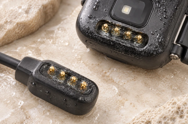
Standardized USB-C accessories bring broad compatibility, while the receptacle still occupies enclosure and PCB space and undergoes repeated insertion and removal. Wireless charging removes that mechanical charging connection, but adds coils and dedicated electronics; alignment and thermal behavior affect its performance. Each approach has limitations that need to be considered alongside the product's engineering priorities.
Selecting an Interface for an OEM Device
Consider magnetic pogo pins for a compact custom device when automatic alignment, frequent docking, tailored geometry, breakaway behavior or configurable power and signal contacts matter. Start by defining the electrical functions. Then choose the magnetic charging cable pin count, pitch, current, working stroke, magnetic force, plating and mechanical structure needed to support those functions.
magnetic charging cable pin countUSB-C is a practical candidate when standardized accessories, wide compatibility and established power and data functions are priorities. Wireless charging may suit a product that needs no external charging connector and has room for the wireless power system. Before selecting an interface, OEM designers should review seven questions: What charging power is needed? Must the product carry wired data? How much room is available for a connector or coil? Will water or sweat reach the device? How frequently will it be charged? Is compatibility with widely available accessories important? Does it need a custom docking experience?
Select the charging interface against the complete product specification, including how it will be used.
Putting the Requirements Together
The three approaches address different design needs. Magnetic pogo pins allow flexible geometry, magnetic alignment and configurable electrical contacts. USB-C offers a standardized ecosystem for power and data, while wireless charging removes the conductive charging connection and can leave a smooth external surface. For an OEM device, compare power, data, size, environmental protection, mechanical design, accessory compatibility and expected user behavior before choosing the interface. The appropriate method follows those requirements.