
Mounting Magnetic Connectors: Terminations, Retention and Design Checks
Published on July 30, 2026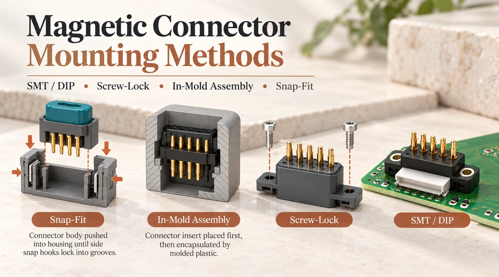
- Why the Mounting Structure Matters
- 1. Surface-mount Termination
- 2. Through-hole Termination
- 3. Screw Retention
- 4. Molded Integration
- 5. Snap-fit Retention
- Comparing the Five Approaches
- Choosing for the Complete Product
- Using Methods in Combination
- Mounting Design Questions
Mounting affects board strength, assembly, sealing, maintenance and service life. Compare surface-mount and through-hole terminations with screw retention, molded integration and snap-fit retention, then select a combination suited to the product.
Why the Mounting Structure Matters
Repeated mating, separation, sideways movement, vibration and impacts load a magnetic interface. Magnetic guidance helps locate the mating halves, but the resulting forces still reach the PCB, housing, solder joints, screws, clips or molded structure around the connector.
magnetic connectorAn unsuitable mounting method may cause:
Cracked or fatigued solder joints
PCB pad lifting
PCBConnector displacement
Poor pogo pin contact
Inconsistent magnetic alignment
Water or dust leakage
Housing deformation
Reduced product service life
Review the electrical connection alongside the path that carries mechanical loads. The mounting structure should support repeated handling without compromising electrical contact.
1. Surface-mount Termination
Surface-mount technology, or SMT, solders the connector terminals to pads on the PCB surface, commonly by reflow. The terminals do not pass through the board; confirm that the selected connector is approved for the intended process.
SMT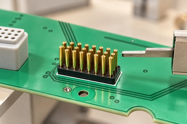
Possible uses include watches, wireless earphones, medical wearables, smart glasses, portable electronics, sensors and other compact products. Application examples do not establish approval for a particular device.
Advantages of SMT Mounting
A small footprint and low profile are useful SMT characteristics. With no electrical terminals passing through the board, the layout can use both sides efficiently, while retaining the necessary mounting and insulation clearances.
Suitable connectors can be placed automatically and reflowed with other board components, reducing manual installation in volume production. Packaging, pickup geometry and the reflow process still require validation.
Additional advantages include:
Small PCB footprint
Low installation height
High assembly efficiency
Compatibility with automated SMT lines
Flexible terminal layouts
Suitable for lightweight products
Engineering Considerations for SMT Connectors
Solder-joint loading is a principal concern. If repeated vertical or sideways handling forces act directly on SMT terminals, solder fatigue or pad separation can result. Design a suitable supporting load path.
Engineers should carefully control:
PCB pad dimensions
Solder paste thickness
Terminal coplanarity
Reflow temperature profile
Connector placement accuracy
Solder fillet quality
Distance between the connector and PCB edge
Larger connectors, higher retention forces or frequent mating may need reinforcement. Consider locating posts or bosses, side solder tabs, brackets, adhesive or support from the enclosure, and verify which features carry the load.
Verify magnets, housing plastics, adhesives and internal components against the actual reflow profile. An SMT designation alone does not establish their heat tolerance.
Best Applications for SMT Mounting
Consider SMT when these requirements apply:
Compact dimensions
Low installation height
Automated PCB assembly
Moderate mating force
High production volume
Minimal manual installation
Space-limited consumer and wearable designs often benefit from SMT, especially where the enclosure can support the connector mechanically.
2. Through-hole Termination
Through-hole technology, or THT, passes terminals or support pins through PCB holes and solders them from the opposite side, using wave, selective or hand soldering as appropriate. This mounting approach is sometimes labeled DIP in connector catalogs; DIP more specifically describes a dual in-line package.
THT / through-hole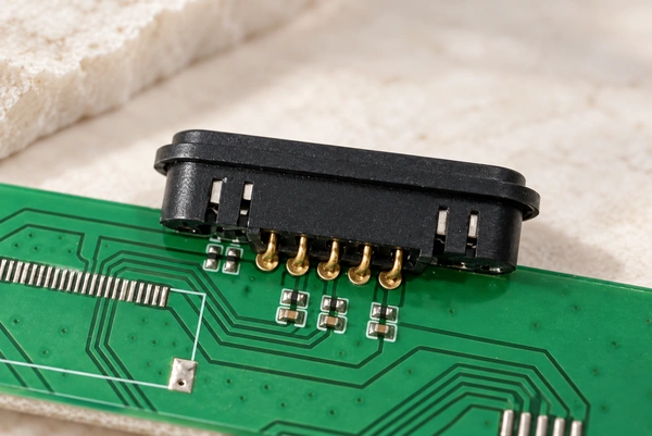
Through-hole magnetic connectors are an option for industrial equipment, docks, control panels and communication products that need robust board retention.
Advantages of Through-hole Termination
Pins anchored through the board can provide better resistance to pulling, tilting and sideways loading than a basic unsupported SMT design. The actual result depends on the terminals, soldering, board and support structure.
A properly soldered through-hole joint provides a physical anchor that can reduce separation risk during repeated mating. Validate the complete load path rather than relying on the hole alone.
Potential benefits include:
Stronger mechanical retention
Better resistance to lateral force
Stable positioning during soldering
Suitability for larger connectors
Greater tolerance for repeated connections
Easy integration of positioning posts
Through-hole terminals may permit larger conductor cross-sections, but the mounting method does not set the current rating. Check contact diameter, conductor size, resistance, materials, plating, PCB copper, wiring and allowable temperature rise.
Engineering Checks for Through-hole Connectors
Board holes constrain routing on both surfaces and can affect internal copper layers. Reserve the required clearance around terminals and include those constraints in the PCB layout.
Important design factors include:
Hole diameter and tolerance
Pin diameter
Annular ring size
PCB thickness
Solder filling ratio
Distance between electrical pins and support posts
Wave or selective soldering temperature
Accessibility for inspection and rework
Large terminals draw heat from the soldering process. Supply enough energy for the required hole fill while keeping the housing and magnets within their thermal limits.
Where Through-hole Termination May Fit
Consider through-hole mounting for these requirements:
Higher mechanical strength
Frequent mating cycles
Larger connector dimensions
Stronger PCB retention
Industrial or semi-industrial reliability
Better resistance to vibration and impact
Charging bases and docks may benefit where users repeatedly place, remove or tilt the mating device. Check the retention structure against those actual movements.
3. Screw Retention
Screws can secure a connector to the board, panel, bracket or housing. Its electrical termination can independently use SMT, through-hole pins, soldered wires, crimps or another suitable method.
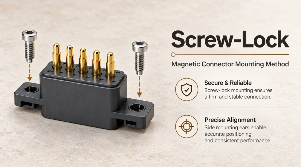
Screw retention describes mechanical attachment; SMT and THT describe electrical termination. They can therefore be used together.
Advantages of Screw-Lock Mounting
A screw-supported layout can route mating and release loads into the fasteners and housing, reducing reliance on solder joints. Verify that the geometry provides the intended load path.
This approach is worth considering for larger interfaces, high-current systems, industrial products, vehicles, robots and outdoor equipment. Those applications still need their own electrical and environmental validation.
Its main advantages include:
High mechanical strength
Strong vibration resistance
Good protection for solder joints
Easy connector replacement
Stable panel positioning
Compatibility with sealing gaskets
Suitability for heavy cables and large magnets
Controlled fastener compression of a gasket or O-ring can support a sealed interface. The assembly must be tested before assigning an IP rating.
Engineering Considerations for Screw-Lock Connectors
Define a suitable tightening window. Excess torque can crack plastic, deform the connector, compress a seal unevenly or damage the PCB; too little can allow loosening under vibration.
Engineers should define:
Screw type and diameter
Thread engagement length
Recommended tightening torque
Metal insert requirements
Screw-locking adhesive requirements
Washer or spring washer selection
Gasket compression ratio
Flatness of the mounting surface
Service and replacement procedures
Threaded metal inserts may improve the durability of a plastic mounting point, particularly when servicing requires repeated removal. Select the insert and fastening design for that duty.
Add locating features where needed so that screw holes alone do not determine contact alignment.
Best Applications for Screw-Lock Mounting
Screw-lock mounting is appropriate for:
High-current connectors
Industrial robots
AGVs and automation equipment
Medical equipment
Automotive electronics
Outdoor charging systems
Large docking stations
Products requiring field replacement
Fasteners add components and assembly work, but can offer strong retention and convenient replacement when those features are designed and validated.
4. Molded Integration
Place the connector or selected components in the mold before injecting plastic or elastomer around them. Depending on the assembly, this may be described as insert molding or overmolding; the terms describe related processes rather than identical structures.
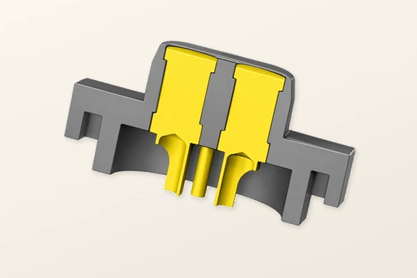
Applications can include magnetic charging cables, sealed modules, wearables, medical products, sensors and custom housings.
Advantages of In-Mold Assembly
Integrating the connector with the molded structure can reduce separate parts, support sealing, form strain relief and create a consistent external finish.
Its key advantages include:
Compact integrated construction
Good resistance to connector movement
Reduced number of assembly components
Potentially improved waterproof performance
Improved cable strain relief
Consistent external appearance
Protection of internal solder joints and wiring
Suitability for customized product shapes
On cable assemblies, suitable overmolding can protect the wire termination and reduce how much bending load reaches a solder joint. Validate the strain relief geometry and material.
Engineering Considerations for In-Mold Assembly
Coordinate connector geometry, mold design, resin selection and process development for molded integration.
Injection pressure and temperature must not displace, distort or degrade the connector. Check the magnet grade at the actual molding temperature, since excessive heat can reduce magnetic strength.
Key process controls include:
Connector positioning inside the mold
Mold cavity tolerance
Injection pressure
Resin temperature
Magnet temperature resistance
Plastic shrinkage
Prevention of resin flash
Protection of pogo pin contact surfaces
Sealing around wires and terminals
Adhesion between different materials
Keep plastic, oil, release agents and other contamination off the contact surfaces. Even small amounts of flash can alter mating height or electrical contact.
Check compatibility between the molding material and housing. Differences in thermal expansion, shrinkage or chemistry can cause stress, cracks or gaps during temperature cycling.
Best Applications for In-Mold Assembly
In-mold assembly is particularly suitable for:
Waterproof charging cables
Medical wearable devices
Smart watches and bands
Compact sensor modules
Outdoor electronic products
Customized cable heads
High-volume products with stable designs
Molded integration usually needs more tooling investment and process qualification. Once developed, it can provide a compact assembly and effective sealing, subject to material bonding and process control.
5. Snap-fit Retention
Molded clips, hooks, tabs or flexible latches retain the connector when it is pressed into its housing and the locking features engage.
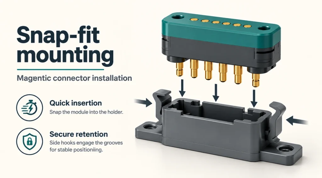
Fast-assembly consumer electronics, docks, replaceable modules, smart home products and plastic housings are possible uses for snap-fit retention.
Advantages of Snap-Fit Mounting
Many snap-fit designs avoid screws and need few tools, reducing parts and final assembly work. Confirm engagement and any required installation tooling for the design.
Its main benefits include:
Fast installation
Low part count
No screw-tightening process
Lower assembly cost
Easy integration into plastic housings
Suitable for automated or semi-automated assembly
Clean external appearance
Snap-fits can be attractive in volume products where rapid assembly takes priority over repeated field disassembly.
Engineering Considerations for Snap-Fit Connectors
Retention reliability depends on resin selection, latch geometry, molding tolerances and the direction of assembly.
Latches need enough flexibility for installation and enough strength to resist movement during mating. Account for creep, fatigue, temperature changes and long-term deformation.
Important factors include:
Clip thickness
Root radius
Insertion angle
Retention angle
Maximum allowable strain
Plastic material and glass-fiber content
Housing tolerance
Connector tolerance
Assembly force
Removal requirements
Vibration direction
Magnetic separation force
Where practical, direct normal operating loads into a rigid housing surface rather than leaving a flexible latch under continuous pull.
A latch intended for initial assembly may weaken or break during repeated removal. Specify and validate removal cycles if servicing is required.
Best Applications for Snap-Fit Mounting
Snap-fit mounting is suitable for:
High-volume consumer products
Plastic charging docks
Smart home devices
Lightweight connector modules
Products with moderate magnetic force
Applications requiring fast final assembly
A snap-fit intended for a sealed product normally needs a separate gasket, adhesive, sealant or controlled seal-compression feature.
Comparing the Five Approaches
| Mounting method | Main advantage | Main limitation | Typical applications |
|---|---|---|---|
| SMT | Compact and automation-friendly | Solder joints may carry mechanical stress | Wearables, earphones, smart glasses |
| THT / through-hole | Strong PCB retention | Requires PCB holes and more board space | Charging docks, industrial electronics |
| Screw-lock | Excellent mechanical strength and serviceability | Additional parts and assembly time | Robotics, automotive, high-current systems |
| In-mold assembly | Integrated structure and strong sealing potential | Higher tooling and process requirements | Waterproof cables, medical and wearable devices |
| Snap-fit | Fast, low-cost assembly | Sensitive to plastic fatigue and tolerance | Consumer electronics and plastic housings |
Scroll horizontally to view every column.
Choosing for the Complete Product
No approach fits every magnetic interface. Review the complete structure and its load paths rather than choosing from connector size alone.
Mechanical Load
Include magnetic attraction, release force, cable weight, handling direction, vibration and the required number of mating cycles in the load assessment.
A small wearable may suit reinforced SMT, whereas a large high-current interface may need screws or a bracket. Use those as design options, rather than fixed rules.
Production Volume
SMT and snap-fits can suit automated volume assembly. Screw retention may add manual operations, while molding needs tooling that can become economical at larger volumes. Compare the actual production processes.
Product Size
SMT often offers a low profile, depending on the part. THT needs board holes; screws need boss and tool clearance. Molding can form an integrated shape but may add mold complexity.
Waterproof Requirements
The mounting method alone does not determine the waterproof rating.
SMT or THT parts may need rear-side adhesive, O-rings, gaskets, potting or enclosure seals. Screws can control gasket compression, while molding can integrate a seal if material bonding and process parameters are controlled. Verify the completed enclosure.
Snap-fit mounting usually requires an additional sealing feature.
Maintenance Requirements
For field replacement, consider screw retention or a snap-fit designed for removal. Permanent assemblies may use molding, adhesive reinforcement or another non-serviceable structure.
Electrical Performance
Establish current capability from the electrical system, rather than the attachment style alone. Verify the following:
Contact resistance
Pogo pin diameter
Terminal cross-section
Pin quantity
PCB copper area
Cable size
Allowable temperature rise
Duty cycle
Ambient temperature
Strong mechanical retention cannot correct an undersized electrical contact or conductor system.
Using Methods in Combination
Many finished magnetic interfaces combine two or more attachment or termination methods.
An industrial interface might combine through-hole electrical terminals, screw retention and a gasket. A wearable might use SMT contacts, locating posts and adhesive reinforcement. A cable head might combine soldered wires with overmolding for sealing and strain relief. Each combination needs validation for its product.
Assigning electrical, mechanical and sealing duties to suitable features can improve the complete assembly’s reliability.
Mounting Design Questions
Which Mounting Approach Fits the Product?
Choose against connector size, retention force, mating frequency, board layout, environment and maintenance needs. SMT can suit compact electronics; THT can add board anchorage; screws support retention and servicing; molding supports integration and sealing; snap-fits support rapid assembly. The approaches can be combined.
When Does SMT Need Mechanical Reinforcement?
Small, light SMT interfaces can perform reliably when pads, joints and enclosure supports are designed for their loads. For higher retention or frequent mating, consider posts, tabs, brackets, adhesive or housing support to keep excessive force off the solder joints.
How Do SMT and Through-hole Terminations Differ?
SMT terminals solder to board-surface pads, supporting compact layouts and automated assembly. THT terminals pass through board holes and can provide stronger anchorage against pulling and sideways loads than basic unsupported SMT. THT also consumes routing space and requires through-hole processing; compare the complete designs.
How Can Mounting Support a Sealed Interface?
Screws can compress a gasket or O-ring, while molding can integrate the connector into a plastic or elastomer sealing structure. SMT, THT and snap-fit assemblies can also be sealed with suitable adhesive, potting, gaskets or housing seals. An installation method alone does not establish waterproof performance.
Can Electrical Termination and Retention Methods Be Combined?
Yes. A connector can combine through-hole terminals for electrical connection, screws for retention and an O-ring for sealing. A wearable can combine SMT terminals, locating posts, housing supports and adhesive. Allocate each function deliberately and validate the combined structure.
What Needs Verification Before Installation?
Check the footprint, mounting tolerances, orientation, polarity, mating height, soldering temperature, load direction, enclosure support, seals and cycling target. Confirm that operating forces reach an appropriate supporting structure instead of relying entirely on solder joints or electrical terminals.
Planning the Mounting System
Surface-mount and through-hole terminations, screw retention, molded integration and snap-fit retention offer different routes to integrating a magnetic interface.
SMT can support compact automated assembly, while THT can add PCB anchorage. Screws can support retention and maintenance; molding can integrate sealed cable or housing structures; snap-fits can simplify final assembly. Actual strength, sealing and cost depend on the design.
Match the mounting system to dimensions, magnetic force, cycling, environment, sealing needs, production volume and maintenance strategy.
Evaluate the connector, board, enclosure, molding process and load paths as one system. A well-chosen mounting design can simplify production and protect electrical contacts, while validation establishes whether it meets the required service life.