
Two-pin Magnetic Connectors: An Application and Selection Guide
Published on May 25, 2026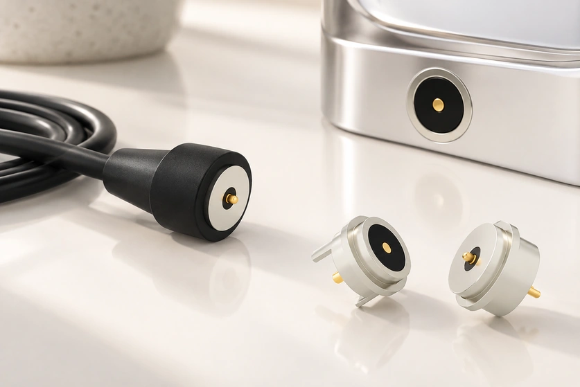
- Understanding a Two-pin Magnetic Interface
- How the Two Contacts Make a Connection
- Benefits and Limitations of Two-pin Designs
- Maintaining a Two-pin Magnetic Connection
- What Affects the Price of a Two-pin Connector
- Specifications and Configuration Comparisons
- RFQ Details and Total System Cost
A two-pin magnetic interface provides quick, self-guided power mating for a compact product that docks frequently. Wearables and AI smart glasses are common examples. This guide reviews construction, application needs, maintenance, specifications, cost drivers and the information needed to compare suppliers.
Understanding a Two-pin Magnetic Interface
This is a two-contact connection, generally built from spring contacts, a housing and magnets. The magnets align and retain the joint while the contacts carry power and, in some specially designed systems, basic signals. Charging cradles, wearables, handheld tools and sealed products can use it where frequent, convenient mating is required.
Video material pending replacement
Construction and Available Variants
A typical two-pin design combines spring-loaded contacts with magnets that guide the halves into their intended polarity and position. The spring system supplies contact pressure while the magnets hold the assembly together. Correct-polarity mating must be established by the particular magnetic and mechanical design.
two-pin magnetic connectorPrincipal Components
Contacts — gold-plated spring pins on the male side or flat mating contacts on the female side.
Magnets — NdFeB magnets for alignment and the specified holding force.
NdFeB magnetsHousing — molded plastic or a metal shell suited to the structural and durability requirements.
Optional sealing — a gasket, potting or an overmold to provide the intended ingress protection.
Application note: two contacts usually serve a basic power connection rather than a complex interface. Their small footprint and low added weight make the arrangement useful in products such as smartwatches and smart glasses where space is limited.
How the Two Contacts Make a Connection
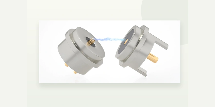
Magnetic attraction brings the mating halves together and guides the pogo pins toward their pads. Spring force maintains the electrical contact and magnetic force provides retention. Current passes through the two contacts. A suitably designed breakaway interface can release under a lateral pull to reduce cable strain and device damage; release behavior must be verified for the application.
Video material pending replacement
Mating Sequence and Current Path
The goal of a well-designed two-pin interface is consistent contact force with little need for precise manual positioning during docking.
Typical Operating Steps
Approach — bring the halves into the short-distance magnetic capture range specified by the design.
Alignment — the magnetic field guides the mating surfaces into position.
Compression — the pogo pins compress to establish the required contact force.
Conduction — current flows through the contacts; resistance depends on plating, pressure and cleanliness.
Release — a lateral pull or impact can separate a designed breakaway joint and help limit damage.
Design Checks Before Integration
Dimensions and geometry — ensure that the mating structures fit correctly, since positional error can damage the pins.
Current and voltage — check the electrical ratings against the physical size and thermal path, which can limit allowable current.
Plating — powered contacts exposed to sweat can suffer electrochemical damage; specify an appropriate coating method and thickness for the wearable environment.
EMI and noise — two-contact data arrangements are uncommon and have interface limitations; assess any needed filtering for the particular system.
Design note: magnetic guidance simplifies mating, but contact angle and plating still need careful review. An unsuitable approach angle or coating can shorten the connection’s service life.
Benefits and Limitations of Two-pin Designs
Self-alignment makes repeated charging convenient, while surface mating can reduce wear from inserted plugs. A two-pin interface can also support a sealed enclosure without a conventional open port. Planned breakaway behavior may help protect a product when its cable is snagged or pulled; the complete design determines whether those benefits are achieved.
Potential Advantages
User handling — a compact, lightweight interface uses little space and can suit wearable, medical and consumer products.
Mating life — suitable contact designs can be specified for tens of thousands or, in particular validated configurations, hundreds of thousands of cycles; this is not a universal life rating.
Environmental integration — a smooth surface without protruding connectors can support a dust-protection strategy, provided the complete enclosure is sealed appropriately.
Docking — magnetic attraction can guide attachment to a dock, charging cable or accessory.
Breakaway — an appropriate release design can reduce damage from trips, snagging and lateral cable loads.
Limitations to Include in the Design Review
Retention can be lower than that of a locking connector in strong vibration unless the design addresses the required holding load.
Magnets can attract metal particles in an industrial environment.
Maximum current depends on contact dimensions, plating and the available thermal path.
Two pins are generally unsuitable for a conventional high-speed data interface.
Environment note: machining areas and workshops can expose the interface to metal shavings. Consider recessed contacts and a defined cleaning procedure, since attracted particles can keep the contacts apart and cause intermittent charging.
Maintaining a Two-pin Magnetic Connection
Keep the contact faces dry, clean and free of attracted metal particles. Inspect the coating and spring return, and avoid unintended lateral loading during attachment. Use a material-compatible cleaning method so that contamination and wear do not progressively increase resistance and heating.
magnetic connectorAn Inspection and Maintenance Checklist
A consistent routine helps address contamination and contact wear before they cause an unreliable charging connection.
Recommended Checks
Visual condition — inspect for discoloration, pitting and scratched plating.
Debris — remove ferrous particles from the magnet area and contact pads.
Cleaning — use a swab that does not shed lint; use IPA (isopropyl alcohol) only where compatible with the assembly materials and permitted maintenance method.
isopropyl alcohol (IPA)Spring operation — verify that the pogo pins return smoothly and evenly.
Thermal condition — investigate unusual warming during charging, which can indicate higher resistance; avoid handling a dangerously hot powered interface.
Handling and storage — keep the assembly dry and protect it from chemicals or liquids outside its specified operating and storage conditions.
Practices to Avoid
Abrasive cleaning or sandpaper on plated contacts.
Excess lubricant that retains dust and interferes with contact.
Twisting or levering the connector sideways while it is energized.
Troubleshooting note: when charging drops out, inspect and clean both mating faces using the permitted method before deciding to replace components. Contamination is one possible cause and should be distinguished from contact damage or an electronics fault.
What Affects the Price of a Two-pin Connector
Price depends on the current requirement, plating thickness, magnet material and coating, sealing, cable or overmold complexity and order volume. A simple two-pin pogo interface generally costs less than a sealed, high-current custom assembly. Bespoke tooling may also introduce an initial NRE charge.
Factors That Change a Quotation
Mechanical complexity and the required level of reliability are major influences on the price of the complete interface.
Requirements That Can Add Cost
Higher current — larger contacts, improved heat dissipation and tighter resistance control.
Thicker gold plating — a coating specification intended to provide the required corrosion and wear performance.
gold platingHigher IP protection — gaskets, potting and more precise housings.
Custom cables — specified length, strain relief, jacket material and overmolding.
Magnet corrosion protection — an appropriate coating for sweat or salt exposure.
Tighter tolerances and testing — contact-resistance screening and the required cycle tests.
Ways to Control Cost
Use standard contact pitches and housings where they fit the product.
Match plating to the actual expected mating-cycle and environmental requirements.
Use a simple nonsealed indoor design where the application genuinely permits it.
Cost note: compare the unit price with the total system cost. A better-suited interface may reduce rework or warranty-related expense, but any saving should be assessed for the specific product rather than assumed from the connector grade.
Specifications and Configuration Comparisons
A suitable two-pin connector balances electrical capacity, wear resistance, corrosion protection and convenient alignment. Compare contact resistance, rated current, plating thickness, magnetic retention, ingress protection and life-test evidence. Sweat, dust and vibration requirements are particularly relevant when trying to prevent early wear or charging interruptions.
Illustrative Configuration Paths
These configuration examples illustrate selection trade-offs. The current and cycle figures require verification for the chosen assembly and test conditions; they are not a fixed range or rating for all two-pin products.
| Specification area | Entry-level two-pin interface | Mid-range two-pin interface | Rugged or sealed two-pin interface |
|---|---|---|---|
| Example application | Indoor consumer accessories | Wearables and small devices | Industrial, medical and outdoor products |
| Illustrative rated current | 0.5–1 A | 1–3 A | 3–5 A+ (design-dependent) |
| Contact plating | Thin Au over Ni | Moderate Au over Ni | Thicker gold or composite plating |
| Magnet retention / source configuration note | Light retention | A coating is specified; holding force is not stated | A special coating is specified; holding force is not stated |
| Ingress-protection approach | Not waterproof | Add a sealing system and verify it | Injection molding with the specified environmentally compatible adhesives; verify assembled protection |
| Illustrative mating-cycle life | 10000~50000 | 50000~100000 | 100000+ |
| Selection priority | Lowest cost within this comparison | A balance of requirements and cost | Reliability under demanding conditions |
Scroll horizontally to view every column.
Selection note: service life and dependable contact result from several interacting parameters. Choose them for the particular industry and operating conditions instead of using a single specification for every application.
RFQ Details and Total System Cost
A purchasing decision should align the load, service life and environment with a supplier’s design and test capability. Check resistance stability after cycling, corrosion performance and magnet durability. A clear RFQ helps expose potential rework, cable failures and field-return costs before the design is committed.
Information for an RFQ and Price Comparison
Provide the following details when asking Magtor or another supplier to evaluate the interface.
Magtor- Electrical requirements
Voltage, continuous and peak current, and duty cycle.
Maximum acceptable voltage drop and temperature rise.
Connection under load and inrush conditions.
- Mechanical requirements
Required mating-cycle life, for example 10k/50k.
Retention force and intended breakaway behavior.
Mounting arrangement: PCB, panel, cable end or a docking cradle.
- Environmental conditions
Target IP rating, sweat or salt-fog exposure and cleaning chemicals.
Operating temperature range.
Exposure to dust and metal particles.
- Materials and reliability
Plating specification, including Au thickness, base material and corrosion requirements.
Magnet grade and its coating.
Required validation: mating cycles, salt fog, vibration and drop testing.
- Product integration
Cable length, overmolding, strain relief and connector orientation.
Packaging, protective caps and shipping measures that keep debris off the interface.
Quotation note: connector cost follows the application specification. Detailed requirements help the supplier propose an appropriate configuration and avoid unnecessary features or hidden integration waste.
Selecting a Suitable Two-contact Interface
Two-pin magnetic mating is a useful option for frequent charging and low-voltage power where easy alignment, reduced insertion wear and an optional sealing strategy matter. Selection still requires the correct current capacity, environment, plating, magnet design and life-test evidence. Share the voltage and current, IP target and cycle requirement with Magtor to discuss a configuration suited to the product.