
Choosing the Right Magnetic Connector Pin Count
Published on June 5, 2026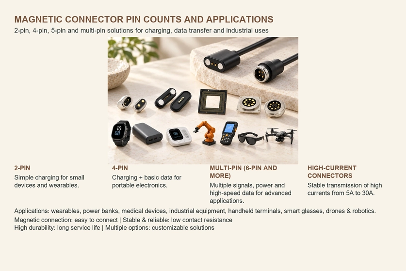
- Two-contact Magnetic Interfaces
- Four-contact Magnetic Interfaces
- Five- to Ten-contact Interfaces
- Interfaces with Ten or More Contacts
- High-current Magnetic Interfaces
- Sealed Magnetic Interfaces
- Matching the Type to the Requirement
A magnetic connector’s contact count should follow its required power and signal paths, not the appearance of the device alone. Current capacity, data requirements, available space, mating life, exposure and user handling all affect selection. This guide compares common contact arrangements with high-current and sealed designs, which are additional design requirements rather than pin-count categories.
Magnetic connectors1. Two-contact Magnetic Interfaces
Application examples:
Smart wearables.
Pet trackers.
LED lighting.
Small rechargeable products.
Electric toothbrushes.
Potential advantages:
A simple positive-and-return charging path.
Compact contact geometry.
A lower-complexity manufacturing arrangement.
Straightforward magnetic alignment.
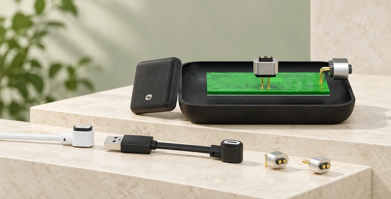
Two contacts suit a design requiring only positive and negative power paths. They do not provide separate simultaneous paths for several signals in addition to that supply. For a suitable charging-only product, this can offer a compact, cost-conscious interface; any additional communication function needs its own circuit-level evaluation.
two-contact magnetic connector2. Four-contact Magnetic Interfaces
Application examples:
Shared power banks.
Charging docks.
Handheld electronics.
Portable medical equipment.
Smart-home products.
Potential advantages:
Charging plus a compatible basic communication arrangement.
Additional options for distributing power and return paths.
A repeatable docking interface when correctly designed.
A structure that can be validated for frequent connection cycles.
Four-contact magnetic interfaces are a practical option for consumer-device charging systems when the contact assignment supports the required power and communication functions. Suitability depends on the actual pinout and assembly performance.
four-contact magnetic connector3. Five- to Ten-contact Interfaces
Application examples:
AR/VR devices.
AI smart glasses.
Industrial handheld terminals.
Medical monitoring equipment.
Smart docking stations.
Potential advantages:
Several distinct signal paths.
Power and supported high-speed data, where the complete interface is designed and validated for it.
Application-specific contact assignments.
More electrical functions within a constrained interface area.
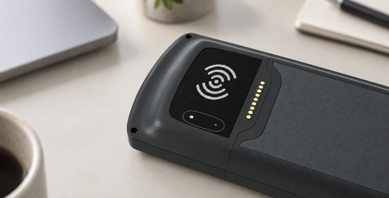
Additional contacts can serve charging alongside more complex signal arrangements. Allocate each path to the required function, then check grounding, layout and signal integrity; contact count alone does not prove support for a data protocol or rate.
4. Interfaces with Ten or More Contacts
Application examples:
Drones.
Robots.
Industrial equipment.
Handheld devices.
Potential advantages:
Several power and signal functions in one interface.
A layout combining different contact sizes where appropriate.
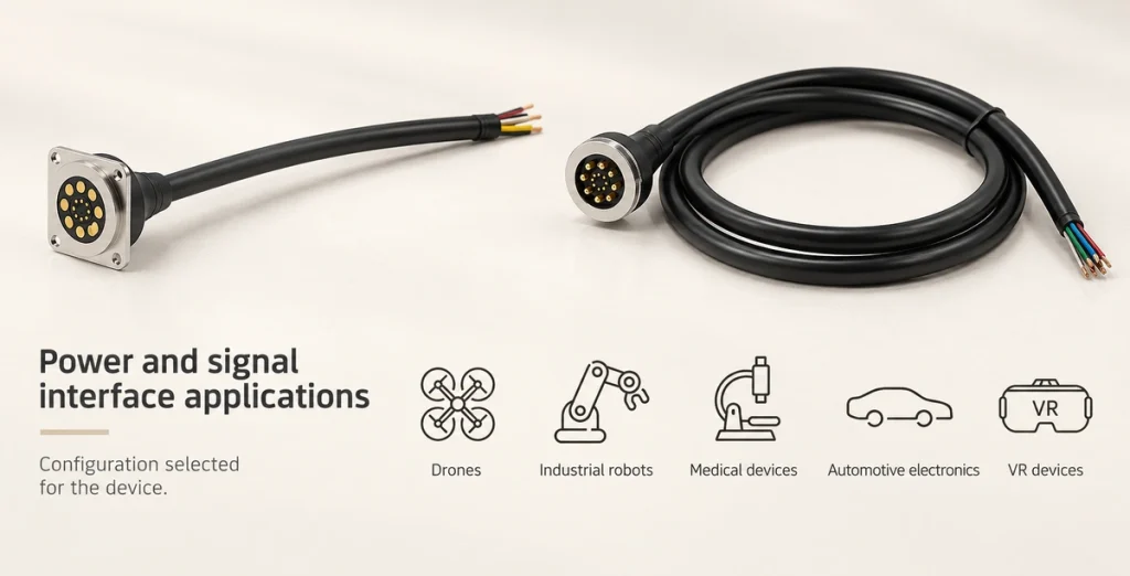
A custom array may use many more than ten contacts, including hundreds in a sufficiently large and suitable structure. That is a possible architectural approach rather than an unlimited capability of every connector: dimensions, alignment, force, routing and manufacturing constraints still need review.
5. High-current Magnetic Interfaces
Application examples:
Portable power stations.
Robotics.
Industrial equipment.
Battery systems.
Automated guided vehicles, or AGVs.
Potential advantages to validate:
Designs intended for 10A–30A or higher, with model-specific thermal validation.
Magnetic retention appropriate to the operating load.
A low-resistance contact path.
Stable operation at the specified electrical and mechanical load.
A high-current design may combine larger power contacts with smaller contacts for lower-current or signal functions. This can concentrate contact material where it is needed and reduce unnecessary size or cost. Verify the entire power path, current sharing and temperature rise rather than inferring capacity from contact size alone.
6. Sealed Magnetic Interfaces
Application examples:
Outdoor electronics.
Marine equipment.
Medical devices.
Wearable products.
Industrial sensors.
Potential advantages of the specified sealing design:
Protection against the stated dust and moisture exposure.
Reduced corrosion exposure at protected parts.
Improved service reliability when the sealing and materials match the environment.
A sealed design may suit exposure that would damage an unprotected connector. However, the spring-pin or cable-side half may remain unsealed while the device-side structure is protected. Do not assume that an advertised IP rating permits live, exposed contacts to supply power underwater; define the protected parts, mated state and test conditions explicitly.
Matching the Type to the Requirement
| Application requirement | Connector option to evaluate |
|---|---|
| Simple charging | Two-contact magnetic interface |
| General electronic equipment | Four-contact interface with a matching pinout |
| Power plus several data or signal paths | Five- to ten-contact magnetic interface |
| 5A–30A high-current output | A model validated for the specified high-current load |
| Outdoor or wet exposure requiring IP65–IP67 | A suitably sealed and tested magnetic interface |
Scroll horizontally to view every column.
Conclusion
Match the contact arrangement to the required functions, then specify the current, environment and life target separately. Two or four contacts can suit simple charging or a limited power-and-signal arrangement, while larger arrays provide more routing options. High-current and sealed structures need their own validation. A well-matched design can support dependable operation and convenient handling without treating any pin count as a performance guarantee.