
Selecting a High-current Magnetic Connector
Published on July 13, 2026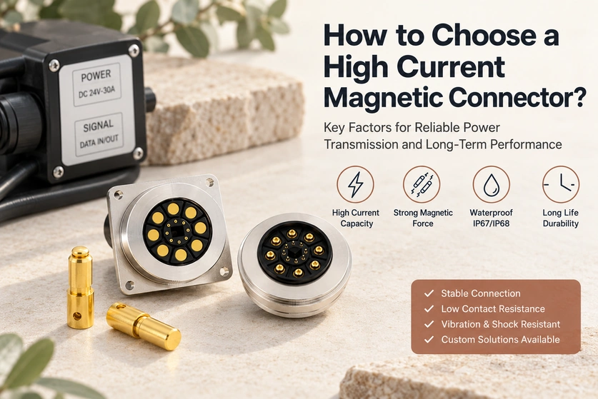
- Specify the Current Profile
- Review Contact Resistance
- Define Holding and Release Force
- Allocate the Contacts
- Verify the Sealing Requirements
- Define Mating Life
- Specify the Operating Environment
- Review Protection Features
- Identify Customization Needs
- Assess the Supplier
- A Final Selection Checklist
A high-current magnetic interface needs a matched electrical path, retention structure and protection arrangement. This guide covers current, resistance, magnetic force, sealing, life and customization, with supplier checks that help engineers and buyers define a testable specification.
high-current magnetic connectorSpecify the Current Profile
Begin with the application’s maximum continuous load and its operating conditions.
Illustrative continuous-current categories in this discussion are:
| Continuous-current example to verify | Application examples |
|---|---|
| 3A–5A | Suitable wearables and handheld electronics |
| 5A–10A | Charging docks and industrial controllers |
| 10A–20A | Power tools and battery packs |
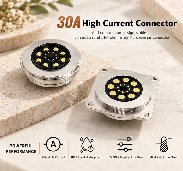
| 20A–30A+ | Robotics, medical equipment, AGVs and energy storage with the required qualification |
Scroll horizontally to view every column.
Selection points to discuss:
The source suggests a 20–30% margin above normal current as a planning example. Agree the actual margin from the load, duty cycle, ambient conditions and validated temperature rise; this percentage is not sufficient for every application.
Specify continuous and peak current separately, including transient duration.
A higher load may require a larger conductive area and revised spring/contact design; stronger springs alone do not establish a higher rating.
Verify the individual contact rating. A 3A-per-pin example must not be confused with a complete connector rated above 3A, and parallel contacts need a current-sharing review.
A mix of larger power contacts and smaller signal contacts may avoid unnecessary size and cost, subject to the actual design.
Review Contact Resistance
Resistance affects voltage drop and heating under load. Set the permitted value from the actual application rather than choosing an unspecified high-performance label.
A suitably low-resistance path can help achieve:
Required loaded power efficiency.
Temperature rise within the specified limit.
Limited resistive energy loss.
Contact conditions compatible with the intended service life.
Contact-system features to review include:
An appropriate gold-plating system.
Controlled contact machining and dimensions.
Spring force within the specified working range.
Define Holding and Release Force
The retention arrangement must keep the intended contact engagement during normal operation.
Include these use conditions in the force review:
Equipment vibration.
Cable movement.
Accidental pull loads.
Docking frequency.
Insufficient force can permit intermittent separation, while excessive force can make release difficult. Check the chosen magnet grade’s assembly and operating temperature limits, because exceeding them can reduce magnetic performance.
The illustrative design discussion spans about 300 gf to more than 2 kgf. Select and measure the force for the actual geometry and release direction; the range is not a capability statement for every model or the approved product series.
Allocate the Contacts
An interface may include several paths for power and supported signals. The contact assignment, not the count alone, determines the functions.
Example allocations include:
Two contacts — positive supply and return for charging.
Three contacts — power, return and one implemented signal.
Four to six contacts — a compatible charging and communication arrangement.
Eight or more contacts — power plus additional data paths, with high-speed support only where the complete interface is designed and validated for it.
A mixed-size layout may use:
Larger contacts for the required power load.
Smaller contacts for the assigned signals.
That layout can use material and space where needed instead of making every contact a large power pin. Verify actual thermal behavior, routing and cost before claiming an improvement.
Verify the Sealing Requirements
Outdoor or harsh exposure may require a defined sealing arrangement. Choose it from the real environment rather than assuming every such application needs the same protection.
Possible IP targets include:
IP65 — dust-tight and protection against the specified water-jet test.
IP67 — temporary immersion under the applicable test conditions.
IP68 — immersion under agreed specified conditions, not unlimited long-term water protection.
Application examples for appropriate sealed designs include:
Outdoor equipment.
Medical devices with their required qualification.
Smart wearables.
Marine electronics with the relevant exposure requirements.
Industrial automation.
Define Mating Life
Frequent engagement produces contact movement and wear, so life needs an explicit target.
Example targets to validate include:
10,000 cycles.
30,000 cycles.
50,000+ cycles where required for the industrial design.
A longer-life contact may reduce servicing when it meets the device’s requirements. Some specialized pogo designs may target hundreds of thousands of cycles, but service life also depends on exposure, working travel, force and allowed performance change, not just equipment age or mating frequency.
Specify the Operating Environment
The environment affects the contact, housing, magnets and mounting over time.
Define the following:
Operating temperature.
Humidity.
Dust exposure.
Required salt-spray performance.
Chemical exposure.
Shock and vibration loads.
Review the contact and housing geometry as well as the material and coating system for those conditions. Validate that the selected structure maintains the required engagement and electrical behavior over the specified exposure.
Review Protection Features
The complete design may need features such as:
Magnetic guidance.
Blind mating within the permitted approach range.
Reverse-polarity prevention and appropriate circuit protection.
Spacing, layout and controls that address short-circuit risks.
Controlled magnetic release at a specified force and direction.
These features can help reduce particular errors and loads when properly implemented. They do not replace safety evaluation of the complete equipment.
Identify Customization Needs
A standard interface may not meet every electrical or integration requirement.
Possible changes to discuss with a capable manufacturer include:
Contact layout.
A design validated for a higher current.
The required sealing structure.
Cable overmolding.
Housing material.
PCB mounting options.
Magnetic holding and release force.
Mechanical locating features.
Customization can improve integration where the changes are manufacturable and tested. It is not automatically simpler or better than a suitable standard part.
Assess the Supplier
Supplier capability influences development, validation and consistent production of the chosen configuration.
Review support and evidence for:
In-house engineering.
Prototype development.
Custom tooling.
Current ISO 9001 and ISO 14001 documentation for the relevant entity and scope, where required.
ISO 9001ISO 14001Electrical and environmental testing.
Production capacity for the planned quantity.
Continued technical support.
Relevant experience can help address development risks, but confirm the proposed design, test plan and production controls directly.
A Final Selection Checklist
Confirm each of these inputs before final selection:
Required continuous current and its conditions.
Allowed contact resistance.
Holding and release force.
Contact allocation.
IP protection and assembly state.
Mating-life target.
Operating exposure.
Electrical and mechanical protection.
Customization scope.
The supplier’s relevant engineering capability.
Conclusion
Select a high-current magnetic interface by defining the electrical load, contact resistance, retention, sealing, life and operating environment together. Review those requirements with the supplier and validate the actual assembly before volume use. Magtor can discuss a standard or custom structure and the evidence needed for your specified power and integration conditions.
Magtor