
Selecting Five-pin Magnetic Connectors for Power and Data
Published on August 5, 2026
- Defining the Five Contact Functions
- 1. Current, Voltage and Resistance
- 2. Contact Pitch and Signal Requirements
- 3. Retention and the Working Position
- 4. Mounting and Cable Routing
- 5. Enclosure Space and Sealing
- 6. Mating Life and Contact Finish
- Preparing a Supplier Specification
- Verifying the Installed Interface
- A Six-step Selection Process
- Five-contact Selection Questions
Size is only one selection input for a five-contact magnetic interface. Assess current, signals, pitch, retention, mounting, sealing and durability together so the chosen assembly can meet its power and data requirements.
5 pin magnetic connectorDefining the Five Contact Functions
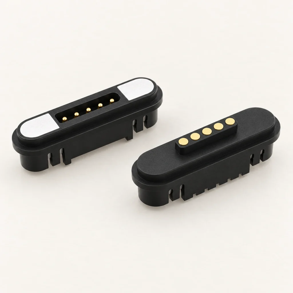
Magnets guide the mating halves while spring-loaded contacts close the electrical paths. Allocate the five contacts to power, return, data, control or detection according to the device circuit; contact count alone does not establish complete circuits.
The table gives example assignments, with reference and return paths to be defined by the circuit:
| Pin Arrangement | Typical Application |
|---|---|
| 2 power + 2 data + 1 detection | Charging, communication, and connection detection |
| 1 power + 1 ground + 3 signal | Low-current devices with multiple control signals |
| 2 positive + 2 ground + 1 signal | Higher-current charging with one control line |
| 2 power + 3 signal | Power supply and sensor or control communication |
| 5 signal contacts | Testing, programming, sensors, or control systems |
Scroll horizontally to view every column.
Before choosing a part, define all five roles and establish whether power and signals operate at the same time. Document the mating view, keying and contact-to-net mapping.
1. Current, Voltage and Resistance
Start with the electrical requirements. Current capability, voltage drop and thermal behavior need to support the intended power path without excessive heating.
Rated Current
Allow appropriate margin between normal operating current and the model’s rating under the actual conditions. Review these inputs:
Continuous charging current
Peak or inrush current
Current per individual pin
Ambient operating temperature
Allowable temperature rise
Number of pins used for power transmission
For a device drawing 1.5 A continuously, a rating of exactly 1.5 A may offer too little operating margin. Select and validate suitable margin for the environment and aging conditions; a higher nominal rating does not eliminate contamination, wear or misalignment faults.
When using parallel contacts, assess resistance and loading differences so that current sharing is acceptable across the complete supply and return circuit.
Rated Voltage
Use operating voltage to determine spacing, insulation, creepage and clearance requirements for the actual environment.
Low-voltage DC project requirements may include the following examples:
5 V
9 V
12 V
24 V
Higher-voltage use requires a fresh review of geometry and insulation performance; do not merely change a rating on the drawing.
Contact Resistance
Lower resistance reduces contact losses and associated heating. Assess these influences on resistance:
Pogo pin diameter
Contact surface area
Spring force
Working compression
Contact alignment
Surface plating
Dust, sweat, oil, or oxidation
Request resistance evidence after mating, salt spray, humidity and temperature exposure, as well as at the initial state.
The most useful specifications include:
Initial contact resistance
Contact resistance under working compression
Resistance after durability testing
Resistance after environmental testing
Maximum allowable resistance increase
A low initial reading does not establish stability after wear or corrosion. Review the full test conditions and allowable change.
2. Contact Pitch and Signal Requirements
A shared power-and-data interface needs a contact layout that suits both its protocol and board design.
PCB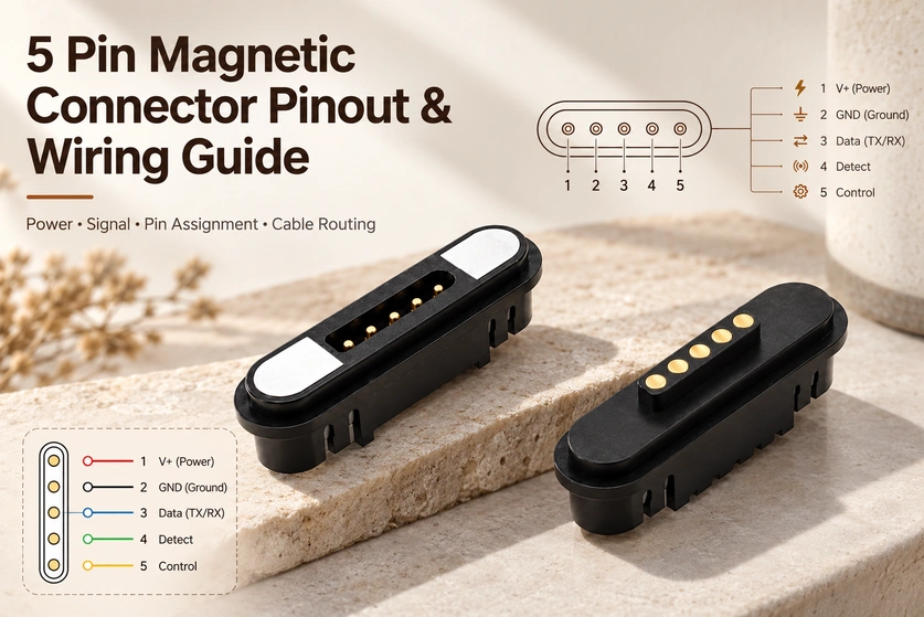
Pin Pitch
Pitch measures the distance between contact centers. Reducing it can shrink the interface while making insulation, routing and assembly more demanding.
A very small pin pitch may result in:
Reduced electrical clearance
Greater sensitivity to contamination
Tighter assembly tolerances
More difficult PCB routing
Higher risk of short circuits caused by moisture
Increased sensitivity to mating misalignment
More spacing can improve isolation and tolerance room, at the cost of enclosure space. Evaluate that trade-off for the product.
The selected pitch should consider:
PCB pad layout
Connector voltage
Power-contact size
Signal isolation
Waterproof structure
Manufacturing tolerances
Available product dimensions
Match the pitch and complete geometry of both halves within the approved tolerances. A mismatch can produce uneven compression, unstable signals or extra wear.
Signal Type
Potential signal roles include the following; the circuit determines which combination is possible:
Device detection
Charging identification
UART
I²C
Low-speed SPI
Analog sensor signals
Temperature sensing
LED control
Motor control
Low-speed differential signals
Give the supplier the protocol, voltage levels, frequency and data rate. “Data transmission” alone is insufficient for technical assessment, and one contact does not automatically provide a multi-wire protocol.
For mixed power and data applications, engineers should also consider:
Signal return paths
Ground pin location
Crosstalk between adjacent pins
Power-line electromagnetic interference
Cable shielding
Twisted-pair requirements
Contact bounce during mating
Cable impedance consistency
A ground contact between power and a sensitive signal is one way to manage interference. Verify the final layout and return paths in the actual device.
3. Retention and the Working Position
Assess magnetic retention with contact compression. Together they influence seating, alignment and electrical stability.
Magnetic Force
Set enough retention to hold during intended use, with a removal force that users can handle. More magnetic force is not always better.
If the magnetic force is too low, the connector may separate because of:
Cable weight
Device movement
Vibration
Accidental contact
Pogo pin spring force
Vertical or side loading
If the magnetic force is too high, it may:
Make removal difficult
Damage the cable
Stress the product housing
Pull the connector away from the PCB
Reduce the quick-release safety function
The appropriate magnetic force depends on:
Product weight
Connector orientation
Cable length
Cable weight
Number of pogo pins
Total spring force
Application vibration
Required breakaway behavior
Wearable and medical products may prioritize a controlled, convenient release, whereas industrial docks or robots may need stronger retention. Define the handling and load requirements for the specific application.
Magnet attraction and assembled pull-off force are different measurements. Magnet arrangement, spring reactions, housing friction, mating angle and pull direction all influence release.
Working Height
Define working height from the approved assembly datum surfaces. In this discussion it means the spacing between specified mating surfaces when the pogo contacts reach their recommended operating compression; it is distinct from working stroke.
It is related to:
Pogo pin free height
Recommended working stroke
Maximum compression stroke
Housing tolerance
PCB tolerance
Adhesive thickness
Waterproof gasket compression
Insufficient compression may cause:
Intermittent charging
Unstable data transmission
Increased contact resistance
Connection failure during vibration
Excessive compression may cause:
Reduced spring life
Pogo pin deformation
Increased surface wear
Excessive mating force
Damage to the PCB or housing
Complete a tolerance stack-up before tooling. Both minimum and maximum assembled conditions must remain inside the recommended working range, rather than relying only on nominal dimensions.
4. Mounting and Cable Routing
The mounting structure influences board layout, assembly, strength, appearance and cable durability.
SMT Mounting
SMT terminals solder to pads on the board surface. Confirm their compatibility with the actual assembly thermal process.
They are suitable for:
Compact electronic devices
Low-profile structures
Automated production
High-volume manufacturing
Provide a supporting load path for cable pulls instead of relying entirely on SMT joints. Housing supports, adhesive, locating posts or other reinforcement may be needed.
THT / Through-hole Termination
Through-hole terminals anchor through the board and can provide greater retention than an unsupported surface-mount arrangement, subject to board, solder and load design.
This method is suitable for:
Frequent mating applications
Industrial equipment
High-vibration environments
Connectors exposed to external force
Wire-Soldered Mounting
Wire-soldered designs terminate directly to a cable, rather than electrically to PCB pads.
They are commonly used for:
Magnetic charging cables
Devices with limited PCB access
Flexible internal wiring
Customized cable assemblies
Protect wire joints with suitable overmolding, adhesive, heat-shrink or strain relief. These features need separate sealing validation if water protection is required.
Panel, Screw-Lock, or In-Mold Mounting
Panel or screw retention can support mechanical loads. Insert molding or overmolding can integrate the housing, finish, seals and strain relief. They are mechanical options that can combine with the chosen electrical termination.
Cable Outlet Direction
Common cable outlet options include:
Straight 180-degree outlet
Right-angle 90-degree outlet
Side outlet
Rear outlet
Customized angled outlet
A straight exit needs rear clearance. A side or right-angle exit can reduce installation depth in wearables, compact devices, wall-mounted equipment and docks, depending on the actual head and cable geometry.
Engineers should evaluate:
Cable bending radius
Internal housing clearance
User pulling direction
Strain-relief length
Nearby component interference
Repeated bending location
Accidental disconnection risk
Provide the cable’s specified bend radius at the exit. Repeated sharp bending close to a solder joint can fatigue conductors and shorten assembly life.
5. Enclosure Space and Sealing
The visible contact face does not show the complete installation envelope. Include the space behind and around the interface.
Housing Space
The product design should reserve space for:
Connector length, width, and height
PCB footprint
Magnet structure
Pogo pin travel
Solder terminals
Cable bending radius
Strain relief
Waterproof gasket
Adhesive groove
Assembly tooling
Housing reinforcement
An interface can fit its exterior opening yet clash internally with components, board edges, batteries, fasteners or cable routing.
Check that the surrounding housing carries the repeated release loads. Thin plastic walls can deform, crack or separate if the load path is unsuitable.
Review these documents before committing to housing tooling:
2D mechanical drawing
PCB footprint
Recommended working height
3D connector model
Maximum tolerance dimensions
Cable assembly dimensions
Waterproof Requirement
Specify sealing for the complete assembled product. A component’s appearance or rating alone does not define the enclosure’s protection.
Possible exposure conditions include:
Rain
Sweat
Splashes
Condensation
Cleaning fluids
Saltwater
Oil
Dust
Outdoor humidity
Common sealing methods include:
O-rings
Rear adhesive sealing
Sealing grooves
Gaskets
Insert molding
Cable overmolding
Protective PCB coating, with separate verification of connector and enclosure sealing
Engineers should confirm:
Is the connector waterproof while connected?
Is it protected while disconnected?
Is the rear side sealed?
Does the IP rating apply to the connector or finished device?
IP ratingWas testing performed after installation?
Can exposed contacts resist sweat, salt spray, and cleaning chemicals?
Ingress protection and contact corrosion are separate requirements. Exposed contacts may corrode and gain resistance even when water is kept out of the enclosure.
For wearable, medical, outdoor, marine or industrial exposure, match seals and contact finish to the actual environment and approved cleaning procedure.
6. Mating Life and Contact Finish
Contact structure, working travel, alignment, force and surface finish all affect durability. Evaluate them as an assembly.
Mating Cycles
Mating life is the number of attachment and release operations completed while meeting specified electrical and mechanical acceptance limits.
The required cycle life depends on the application.
Occasional maintenance differs from daily charging. Shared or rented products, wearables, medical equipment and industrial test fixtures may require greater cycling durability; derive the target from their actual use.
Cycle life is affected by:
Contact alignment
Working compression
Side loading
Contact force
Surface contamination
Mating speed
Electrical load
Plating thickness
Environmental exposure
When reviewing a cycling report, establish these test conditions:
Was the test performed under electrical load?
What compression distance was used?
What was the test speed?
What was the allowable resistance increase?
Were the contacts cleaned during testing?
Was lateral misalignment included?
Was the test performed in a laboratory or application environment?
Unpowered mechanical cycling does not establish performance during repeated loaded charging. Review both relevant operating conditions.
Plating Specification
Gold is a common contact finish for conductivity and resistance to insulating oxidation. Its reliability depends on the entire plating system, not on a gold-colored surface.
Important specifications include:
Gold thickness
Nickel barrier thickness
Base material
Hard gold or soft gold
Selective plating area
Plating uniformity
Surface porosity
Salt-spray resistance
Wear resistance
A thin gold finish may lower cost but can wear through sooner in demanding cycling. Damage can expose underlying material to oxidation and increasing resistance; verify the finish for the duty.
For demanding applications, engineers may consider:
Thicker gold plating
Composite gold plating
Palladium-nickel underlayers
Enhanced corrosion-resistant coatings
Selective thick plating on contact areas
Request thickness measurements, salt-spray evidence, cycling results and resistance measurements after durability exposure. Agree the measurement method and acceptance criteria.
Preparing a Supplier Specification
Complete project information makes it easier to assess an existing part or develop a custom interface against defined requirements.
A typical specification sheet should include:
| Selection Item | Information to Provide |
|---|---|
| Pin assignment | Function of each of the five contacts |
| Electrical requirements | Continuous current, peak current, and operating voltage |
| Signal requirements | Protocol, frequency, voltage level, and data rate |
| Connector dimensions | Maximum length, width, height, and PCB space |
| Pin pitch | Required or acceptable contact spacing |
| Magnetic force | Target retention or pull-off force |
| Working height | Available compression and tolerance range |
| Mounting method | SMT, THT, wire termination, with suitable panel or molded retention |
| Cable structure | Length, wire gauge, shielding, and outlet direction |
| Environmental protection | Waterproof, sweat, dust, salt spray, or chemical resistance |
| Durability | Required mating cycles |
| Plating | Material, thickness, and corrosion-resistance requirements |
Scroll horizontally to view every column.
Verifying the Installed Interface
Evaluate the sample inside the actual product structure before final approval.
Recommended validation tests include:
Current-carrying test
Voltage-drop test
Temperature-rise test
Signal-integrity test
Contact-resistance test
Pull-off force test
Working-height tolerance test
Mating-cycle test
Cable bending test
Vibration test
Drop test
Waterproof test
Salt-spray test
High- and low-temperature test
Simultaneous power and data make system-level testing particularly relevant. Installation can introduce interference, uneven compression or housing distortion even when the isolated component performs well.
A Six-step Selection Process
The selection process can be summarized in six steps:
Confirm the current, voltage, and maximum acceptable contact resistance.
Define the signal protocol, pin assignment, and pin pitch.
Select the magnetic force and working height.
Choose the mounting method and cable outlet direction.
Verify the housing space and waterproof structure.
Specify the mating-cycle life and contact plating.
Neither minimum size nor maximum magnetic force determines a suitable interface. Select a design intended to meet the specified power, data, environmental and service-life requirements, then verify it against those targets.
Five-contact Selection Questions
How Can Power and Data Share Five Contacts?
Allocate power, return, data, control and detection around the circuit’s current, protocol, grounding and interference-control requirements. The contact count does not define the assignment or protocol performance.
How Should the Current Rating Be Confirmed?
General design discussions may cite 1 A to 5 A per contact for some parts, and up to 30 A for specially engineered high-current solutions. Neither is a universal five-pin rating. Confirm the exact contact and circuit path, including diameter, resistance, force, plating, working height, power-contact count and thermal conditions.
What Is Needed for Higher-speed Signals?
Pogo interfaces often carry lower-speed data, detection, controls or sensors. Higher speeds require a suitable pinout, return paths, shielding, cable structure, impedance control and signal tests on the complete system.
How Is Waterproof Performance Determined?
Grooves, gaskets, adhesive, insert molding and cable overmolding can form part of a sealed design. Establish the final IP rating through the specified installed assembly and its tests.
How Should the Mounting Combination Be Chosen?
SMT can suit compact automated board assembly; THT and panel retention may support larger mechanical loads. Soldered wire terminations can combine with overmolding for cables. Select the electrical and mechanical features together for the actual duty.
Which Parameters Can Be Customized?
Custom requirements can include pitch, layout, current capability, retention, mounting, working height, cable exit, seals, plating and housing dimensions. Confirm the feasible combination and its validation plan.
Developing a Defined Interface
For a five-contact power-and-data design, balance electrical capability, signal quality, mechanical integration, environmental protection and service life.
Begin with current, voltage, protocol and contact assignment. Then assess pitch, retention, working position, mounting, housing space, cable route, seals, cycling and the contact finish.
Communicate complete technical requirements early to improve sample relevance and limit redesign risk. Development time, cost and lifetime reliability still depend on the design process and its validation.