
How Many Mating Cycles Can a Magnetic Connector Handle?
Published on August 7, 2026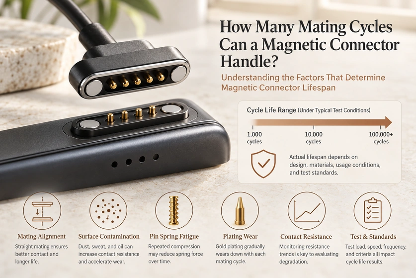
- What affects magnetic-connector cycle life?
- How magnetic contacts connect and release
- Understanding mating, holding and release forces
- How to specify a mating-life target
- Quoting a high-cycle magnetic interface
- Frequently asked questions
There is no single mating-life rating for all magnetic connectors. Published design references may discuss 10,000–100,000 complete mating cycles, with specialised structures targeting up to one million. Those figures depend on plating, spring design, alignment, electrical load and environment, and require model-specific evidence before they become a product rating.
Magnetic connectorsVideo material pending replacement
What affects magnetic-connector cycle life?
Magnet strength, materials, contact geometry, alignment, environment and electrical requirements all influence service life. Assess them together for the charging or communication interface, using test conditions that represent the intended application.
| Factor | Why It Matters | Engineering Impact |
|---|---|---|
| Contact plating | A suitable gold finish can protect the contact surface | Finish performance depends on the plating stack and wear conditions |
| Spring-pin structure | Controls compression and rebound | Supports repeatable contact within its specified travel |
| Magnet alignment | Guides the connector into position | Correct alignment helps reduce side loads and scraping |
| Contact force | Provides contact pressure within the specified compression range | Insufficient pressure can cause dropouts; excessive pressure can increase wear |
| Operating current | Generates heat at the interface | Overload can degrade plating and spring performance |
| Dust, sweat, moisture | Contaminates the contact area | Can raise resistance and reduce service life |
| Cable strain relief | Protects the solder joint and housing | Helps prevent failures at the termination or housing |
Scroll horizontally to view every column.
Magnet strength and material selection
Select attraction sufficient to retain the assembly while allowing the intended release action. Neodymium is a common magnet material; protective magnet finishes and the nickel/gold layers used on electrical contacts have different roles. Specify each material and finish for its own wear and corrosion exposure.
neodymium magnetsContact geometry and alignment
Correct alignment limits unwanted scraping and side loads. The cited example contrasts 10,000 or more cycles with only 3,000–5,000 under lateral loading, but no model or test report accompanies those figures here. Treat them as an illustration of loading sensitivity, not a verified life prediction. One cycle means one complete connection followed by separation.
Environment and service life
Temperature changes, humidity and dust can accelerate degradation. A hypothetical 10,000-cycle rating under one test condition does not guarantee the same result in a harsh environment; failure within hundreds or thousands of cycles illustrates the risk rather than a defined derating rule.
A 10,000-cycle target may cover some consumer usage patterns. Industrial docks, medical equipment, POS terminals, wearables, robotics and frequently docked products can require a higher target. Calculate the actual use frequency and lifetime, then define the full exposure and validation conditions.
Design note: Supplement baseline cycling with exposures relevant to the product, such as sweat or salt spray. These tests help assess failure mechanisms; they do not directly convert into a guaranteed number of field years or mating cycles.
How magnetic contacts connect and release
Embedded magnets assist alignment and retention. Once the halves are properly seated, spring contacts press against the mating surfaces to carry power or signals. The magnetic field holds the assembly; it does not wirelessly transmit electricity through this contact interface.
spring contactsVideo material pending replacement
Three-pin magnetic connector: contact structure and operating animation
The six stages of connection
Approach: The cable-side half moves towards the device-side half.
Attraction: The magnet arrangement draws the mating halves together.
Alignment: Housing features, magnet polarity and contact layout establish the correct mating orientation.
Compression: Spring contacts move within their working travel against the mating pads.
Conduction: The correctly compressed interface carries the assigned power and signals.
Release: The halves separate when the applied force overcomes retention in the relevant direction. Device movement and safe powered separation depend on the full mechanical and circuit design.
| Component | Function |
|---|---|
| Magnet | Provides attraction, alignment, and retention |
| Pogo pin | Maintains spring-loaded electrical contact |
| Contact pad | Receives current or signal from pogo pins |
| Plastic or metal housing | Controls alignment and protects the contacts |
| Cable or PCB termination | Connects the magnetic interface to the circuit |
Scroll horizontally to view every column.
Design note: Match retention and actual pull-off behaviour to the application. Excess attraction can increase stress and defeat the intended breakaway action; evaluate force, direction, device support and cable load together.
Understanding mating, holding and release forces
Mating force describes the force needed along the intended path to seat the halves. Magnet attraction assists approach, whereas spring compression, seals and friction may resist motion. These forces vary with position and direction, so they are not simply all added as positive insertion forces. Holding and pull-off force are separate requirements.
Typical engagement characteristics to compare
| Connector Type | Typical Mating Feel | Main Force Source | Design Concern |
|---|---|---|---|
| Standard USB connector | Insertion resistance depends on the model | Friction and shell engagement | Repeated insertion can wear the mating surfaces |
| Board-to-board connector | Controlled positioning during engagement | Pin/socket engagement | Alignment and contact deformation limits |
| Magnetic pogo connector | Magnet-assisted approach | Attraction acting against spring and other reaction forces | Balance between retention and breakaway |
| Waterproof magnetic connector | Seal compression may increase engagement resistance | Magnetic attraction, spring reaction and seal compression | Validate seal compression and corrosion exposure separately |
Scroll horizontally to view every column.
Force affects contact stability, retention, usability and wear. Too little retention can allow vibration-induced separation; excessive pull-off force may encourage angled removal and stress the cable, housing or contacts. Verify the intended mating and release paths rather than relying only on a magnet specification.
Design note: Account for the combined spring reaction of every contact at its actual working compression and tolerance limits. This matters even in a compact five-pin interface, where a small height change can alter both contact pressure and the user’s release effort.
How to specify a mating-life target
For Magtor design discussions, 10,000–100,000 complete connection-and-removal cycles can serve as reference targets, depending on the model, contact count, finish, electrical load and environment. Custom projects may seek hundreds of thousands of cycles. Confirm any proposed rating against the specific test setup, acceptance criteria and supporting evidence.
Application cycle targets for design review
| Application | Illustrative cycle target; not a universal model rating | Recommended Design Focus |
|---|---|---|
| Consumer charging cable | 10,000–20,000 cycles | Smooth feel and cost efficiency |
| Wearable device dock | 20,000–50,000 cycles | Sweat resistance and compact pin layout |
| Medical charging cradle | 30,000–100,000 cycles | Stable contact resistance and cleanability |
| Industrial handheld device | 50,000–100,000 cycles | Durability, vibration resistance, and plating life |
| Custom Design | Project-specific | Current, signal, size, force, and cycle target |
Scroll horizontally to view every column.
A cycle test repeatedly connects and separates the assembly while checking resistance, wear, retention and visible damage. Reaching the target count is insufficient if electrical or mechanical limits are exceeded along the way. Define measurement intervals and acceptance criteria before testing.
contact resistanceDesign note: Specify the mating angle, speed, current load, humidity, dust exposure and allowable resistance change before comparing cycle numbers. A larger count under a different test condition is not necessarily the more suitable result.
Quoting a high-cycle magnetic interface
A quotation depends on contact count, magnet size, finish thickness, sealing, current requirements, tooling, cable assembly, test scope and quantity. For example, a custom five-pin interface targeting 50,000–100,000 cycles needs its specifications reviewed before either its life claim or price can be confirmed.
Cost drivers to review
| Cost Factor | Simpler specification or supply scope | Additional specification or supply scope |
|---|---|---|
| Contact plating | Standard gold flash | A thicker specified finish where the wear requirement calls for it |
| Pin structure | Standard pogo pin | A spring contact selected for the required cycle test |
| Magnet grade | Basic retention | Application-specific force and controlled magnet polarity |
| Housing | Standard plastic | Custom moulding, seals or structural reinforcement |
| Testing | Basic electrical test | Additional cycle, corrosion, vibration or ageing validation |
| Assembly | Connector only | Cable assembly or overmoulding included in the supply scope |
| MOQ | Higher unit cost at low volume | Production volume may reduce unit cost; it is not a performance rating |
Scroll horizontally to view every column.
Provide electrical requirements, dimensions, a cycle target, environmental conditions and expected annual volume. Magtor can then assess whether an existing design or a custom interface is appropriate; confirm the proposed specification and validation plan before approval.
Design note: Compare quotations against the same cycle conditions, plating system, current requirements, magnetic-force specification, test standard and assembly scope. Unit price alone cannot show whether the interfaces meet equivalent requirements.
Frequently asked questions
What service life should I expect?
Depending on the contact structure, finish, spring, working travel and environment, design references may range from thousands to tens of thousands of cycles, with higher targets for specialised designs. Obtain a model-specific result under defined conditions rather than assigning a general range to every connector.
Which conditions affect service life?
Plating wear, spring fatigue, mating angle, working height, dirt, current load, moisture, dust and corrosion can all limit life. Side loading or compression beyond the recommended range introduces additional mechanical risk.
Can electrical load shorten mating life?
Yes. Removing contacts while they carry current can produce arcing, local heating and erosion, depending on voltage, load and power-control design. Separate an unloaded mechanical-life result from a cycle test conducted under a defined electrical load.
How does the plating system affect durability?
Gold plating can help control oxidation and contact resistance, but wear life depends on the thickness, base layers, contact materials and operating conditions. Specify and validate the whole plating system for frequent mating rather than relying on the word “gold”.
What signs indicate contact wear?
Look for rising resistance, intermittent charging or signals, reduced spring force, visible wear, corrosion and alignment problems. Resistance monitoring is useful during cycling, alongside the defined mechanical and visual acceptance checks.
How should I define a cycle-life requirement?
Estimate connections per day over the planned product life and add an appropriate design margin. Then specify working height, electrical load, mating direction, cycling frequency, environment and failure criteria so the target can be tested meaningfully.
Conclusion
A cycle count is useful only with the conditions and acceptance criteria behind it.
State the mating method, working height, current load, plating, environment, speed, measurement intervals and failure criteria in the durability specification.
Spring fatigue and plating wear are important mechanical degradation mechanisms. Contact resistance helps track electrical deterioration, but it should be assessed with the other specified acceptance criteria.
“How many cycles?” starts the comparison; it does not complete the engineering assessment.
Also ask:
“Under the intended test conditions, for how many complete mating cycles does the interface maintain the required mechanical and electrical performance?”
Share your service-life requirements with Magtor to discuss a suitable design and validation plan. Request the relevant model-specific test evidence and confirm the scope of any simulated-application testing; this guide does not include a supporting product test report.
Magtor