
How Much Current Can a High-current Magnetic Connector Carry?
Published on July 9, 2026
- What Defines a High-current Magnetic Interface?
- Alignment and Electrical Engagement
- Current Examples and Their Design Conditions
- Potential Integration Benefits
- Application Examples
- Selecting the Required Current Rating
Current capacity depends on the contacts, materials, dimensions, termination and thermal conditions of the complete interface. The discussion here includes designs in the 5A–30A+ range per connector, with custom structures potentially serving higher loads. These are design examples: obtain the selected model’s rating, duty cycle and temperature-rise evidence rather than applying the range to every magnetic assembly.
high-current magnetic connectorWhat Defines a High-current Magnetic Interface?
A high-current magnetic interface is designed for a load beyond the intended capacity of a smaller low-power connection. It may use larger conductive structures, suitable materials and a revised thermal path. The magnets guide and retain the halves while the electrical contacts carry power; the required current is established by the complete assembly specification and validation.
magnetic connector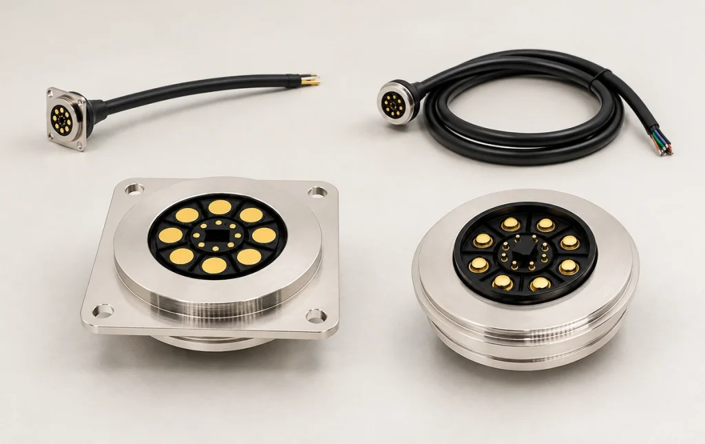
Combining magnetic guidance with spring-contact engagement can make repeated attachment convenient. Contact resistance and performance at load still need to remain within the specified limits.
Alignment and Electrical Engagement
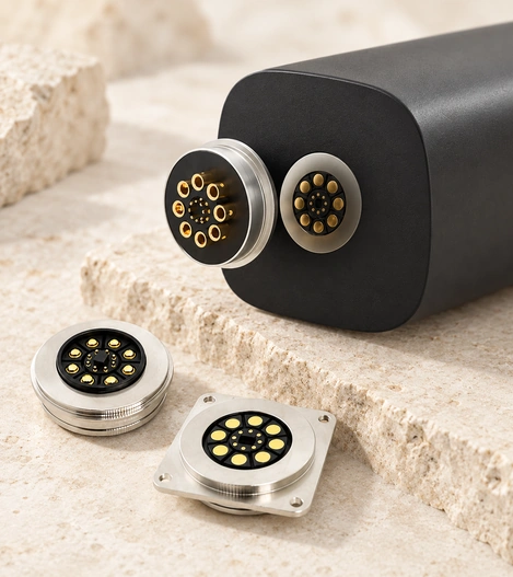
The arrangement combines two complementary functions:
1. Magnetic guidance — magnets and locating geometry align the intended mating faces and retain them. This can simplify frequent attachment, but correct orientation and reverse-mating protection still require design checks.
2. Spring-contact engagement — pogo contacts compress through their working travel to maintain pressure. Validate continuity under the permitted movement, vibration and alignment tolerances.
Possible high-current design measures include:
Larger-diameter pogo contacts.
Several power contacts in a verified parallel arrangement.
A suitably low-resistance contact-material system.
A coating process matched to the current, wear and exposure requirements.
These measures can support current capacity and temperature control when they are coordinated and validated in the final interface.
Current Examples and Their Design Conditions
Contact structure, dimensions, materials and thermal paths all affect the permissible load.
Illustrative categories from the source discussion are:
| Design category | Illustrative current range to verify | Application examples |
|---|---|---|
| Standard magnetic interface | 1A–3A | Wearables and smart accessories |
| Medium-current interface | 3A–10A | Tablets, smart-home devices and portable electronics |
| High-current interface | 10A–20A | Industrial equipment and charging devices |
| Higher-current interface | 20A–30A+ | Robots, drones and suitable energy equipment |
Scroll horizontally to view every column.
Design Factors Behind Current Capacity
1. Contact size and count — larger contacts may provide a larger conductive path. Parallel power contacts can share current when their wiring, engagement and resistance are designed for balanced loading; contact ratings cannot simply be added without checking the complete assembly.
A 16-contact example may combine larger power contacts with smaller signal contacts. The power paths share the intended load only when both supply and return, terminations and thermal behavior are appropriately designed and validated.
2. Contact materials and coatings — options to review include:
Copper-alloy contacts selected for the required conductivity and mechanics.
An appropriate gold-coating system for stable mating resistance and corrosion exposure.
A spring design that supplies the intended contact force.
A stable, suitably low-resistance path helps control heating under load, but the actual temperature rise must be measured for the chosen assembly.
3. Thermal conditions — define:
- The allowed contact resistance.
Connector dimensions and installation.
Heat-dissipation paths.
Continuous load, peak load and duty cycle separately.
A design permitting a short 30A burst may have different conditions from one carrying 30A continuously. Confirm burst duration, cooling and the continuous rating instead of treating the two operating modes as equivalent.
Potential Integration Benefits
1. A Power Path Suited to the Load
A purpose-designed high-current structure can serve charging or power equipment where a smaller candidate interface is insufficient. Verify current, voltage and thermal behavior for the actual product before selecting it.
2. Guided Attachment
Magnetic guidance can simplify engagement, while locating features establish the seated position. Check the intended approach range and mating direction rather than assuming alignment is accurate from every position.
3. Protection for the Operating Environment
Options to specify where required include:
A sealing design targeting IP65, IP67 or IP68 in a specified test state.
IP65 / IP67 / IP68Coatings for the relevant corrosion exposure.
Materials rated for the operating and assembly temperatures.
Mechanical support for the required vibration profile.
Suitability for a demanding environment follows the relevant validation of these features, not the high-current label.
4. Repeated-mating Capability
A face-contact design may limit insertion-related damage. Suitable assemblies can target thousands or tens of thousands of cycles, but confirm the selected model’s working conditions and permissible wear or resistance change.
Application Examples
High-current magnetic designs may be considered for categories such as:
Industrial equipment — handheld terminals, robotics, automation and AGV charging.
Battery and charging equipment — battery packs, portable power systems, charging docks and energy-storage products.
Consumer electronics — suitable higher-power smart products, laptops, tablets and smart-home devices.
Medical and professional equipment — instruments, beauty devices and portable diagnostic equipment with the required application qualification.
Selecting the Required Current Rating
Provide these requirements during selection:
Continuous current in A.
Peak current and its duration.
Operating voltage.
Available mounting space.
Water exposure, vibration and temperature conditions.
The required mating-life target.
The source selection examples use 3A–10A for some consumer products and 10A–30A for some industrial or higher-power equipment. Choose from the actual load and validation conditions rather than assuming those ranges cover most products in either category.
Conclusion
High-current magnetic interfaces combine a suitable power-contact structure with magnetic guidance and retention. A 30A design is among the options discussed by Magtor, but the exact model, duty cycle, voltage and thermal conditions must support that load. Review contact resistance, terminations and protection together for a robot, drone, battery system or other demanding device, then validate the completed assembly.
Magtor