
How Magnetic USB Cables Work: The Detachable Contact Interface
Published on August 14, 2026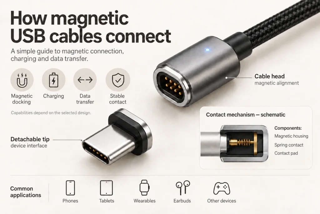
- The detachable-tip arrangement
- How the contacts carry power
- Checking data capability
- Convenience and design checks
- Comparison with a conventional USB cable
- Spring contacts in the magnetic interface
- Custom-cable inputs for OEM products
- From an adapter to an integrated interface
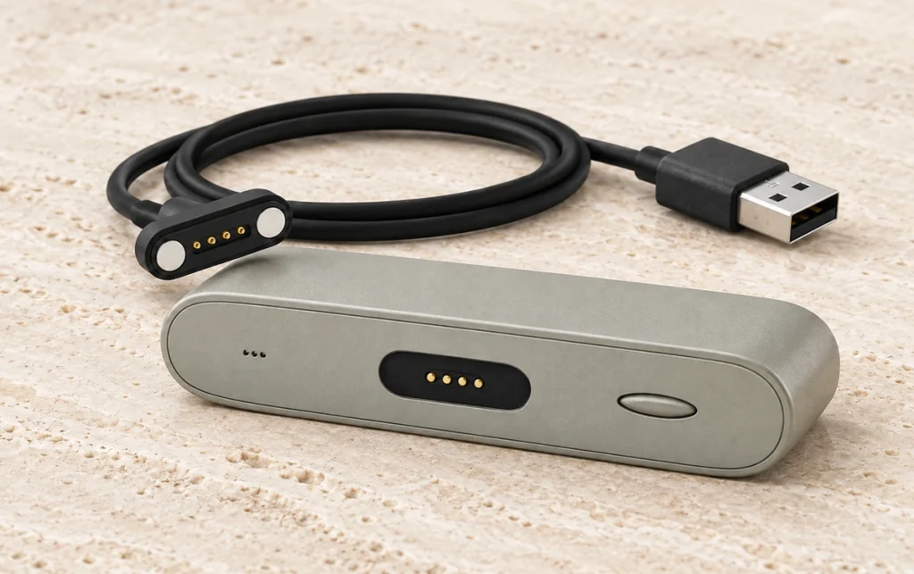
A magnetic USB cable separates at a magnetic joint instead of requiring removal of the device-side plug each time. A compatible USB-C, Micro USB or other tip may remain in the device. When the cable end engages that tip, physical contacts carry power and, in a design that supports it, data.
magnetic contact jointThis is a conductive cable connection. Magnets assist positioning and retention; they do not transfer charging energy wirelessly.
The detachable-tip arrangement
Two main assemblies form a typical system:
USB cable → magnetic cable end ↔ compatible detachable tip → device
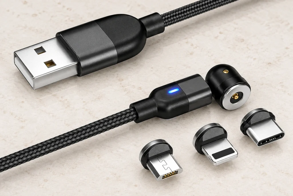
The tip uses the device’s matching plug interface and may stay in its port. Repeated connection then occurs at the magnetic joint, subject to the tip’s mechanical fit and the system’s electrical compatibility.
USB-CMicro USBSome systems supply several compatible tip types for one cable. That does not make tips from different magnetic systems interchangeable or establish compatibility with every device.
The magnets hold and guide the halves. The conductive surfaces form the electrical connection.
How the contacts carry power
Within the designed approach range, attraction helps bring the cable head and tip into their intended position.
Correctly engaged contacts complete the intended path:
Compatible supply → USB cable → magnetic contact joint → device-side adapter → device power circuit
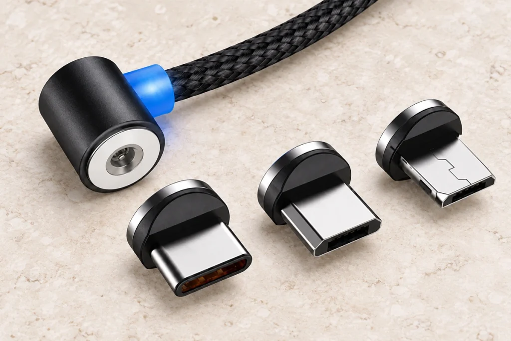
Positive and return contacts carry current. USB source detection, charging identification or other control paths must also meet the system requirements; two conductors alone do not establish universal USB charging.
The intended engagement sequence is:
The compatible detachable tip remains seated in the device.
The cable end approaches the tip.
Magnets and mechanical geometry guide the mating halves.
The required contacts engage correctly.
The compatible source and device controls permit charging through the cable.
Removal can occur at the magnetic joint while the original USB tip remains in the port. Verify the release force and direction so the device is not pulled or damaged.
That arrangement can simplify frequent charging connections, with actual wear and handling assessed for the product.
Checking data capability
Some magnetic cables carry data as well as power; others are charging-only. Confirm the exact cable and tip specification.
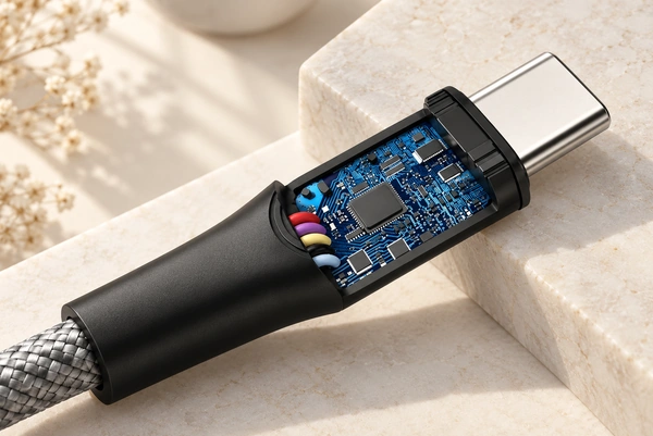
A charging-only cable still needs the power and control paths required by its implementation. Application-data transfer additionally needs the appropriate signal conductors and electrical design.
A charging-and-data claim should be checked against model documentation and relevant tests rather than assumed from the product name.
Data and power behaviour depend on:
Number of electrical contacts
Contact arrangement
Cable construction
Contact resistance
Signal routing
USB protocol
Power-delivery design
Shielding and signal integrity
The label “magnetic USB cable” does not specify USB data support, Power Delivery, a data rate or charging wattage. Those are separate characteristics of the actual design.
Confirm each characteristic for the complete cable-and-tip combination.
USB-IF defines electrical, mechanical and compliance requirements for USB connectors and cable assemblies. A USB-C plug at one end does not automatically make a proprietary magnetic mating interface a standard or certified USB-C connection.
Convenience and design checks
The detachable joint changes the connection routine.
Moving the cable end into its capture range can reduce plug-positioning effort. The permitted distance, angle and final alignment still depend on the actual magnets and housing.
Four possible handling benefits are:
Quick engagement: Suitable guidance and geometry can permit one-handed attachment without conventional plug insertion.
Less port insertion: Leaving the tip seated reduces repeated insertion at the original USB port. Protrusion and side loads still need assessment, and the port is not immune to wear.
Controlled release: A magnetic joint can separate during a pull, provided its release force and direction suit the supported device.
Tip choices: Some systems accept their own compatible USB-C, Micro USB or other tips; this is not cross-system interchangeability.
Check contact cleanliness, attraction and release force, current limits, resistance, tolerances, signal requirements and compatibility. Exposed contacts can also require protection against conductive debris and partial engagement.
Comparison with a conventional USB cable
The magnetic design adds a separate mating location:
| Feature | Standard USB Cable | Magnetic USB Cable |
|---|---|---|
| Connection | Direct plug insertion | Magnetic detachable interface |
| Alignment | Plug positioning and insertion | Magnetic assistance with defined contact geometry |
| Electrical transfer | Metal contacts | Metal contacts |
| Quick release | Removal normally occurs at the inserted plug | Release can occur at the magnetic joint; validate its behaviour |
| Detachable tip | Usually no | Common |
| Charging | With a compatible source, cable and device | With a compatible source, cable, tip and device |
| Data transfer | Depends on cable and device implementation | Depends on the complete magnetic cable and tip design |
| Customization | Uses the specified USB connector interface | The proprietary magnetic geometry and pinout must match |
Scroll horizontally to view every column.
Both use conductive contacts to carry electrical power.
The magnetic version adds another contact joint between cable and adapter. Account for its resistance, alignment, tolerances and engagement sequence in the system review.
Spring contacts in the magnetic interface
Some magnetic cable designs use them; others use different contact structures.
Spring-loaded pogo pins with matching pads and magnets are one way to build a conductive detachable interface.
A possible arrangement is:
USB-A or USB-C termination → cable → magnetic housing → spring contacts ↔ mating pads → device or detachable adapter
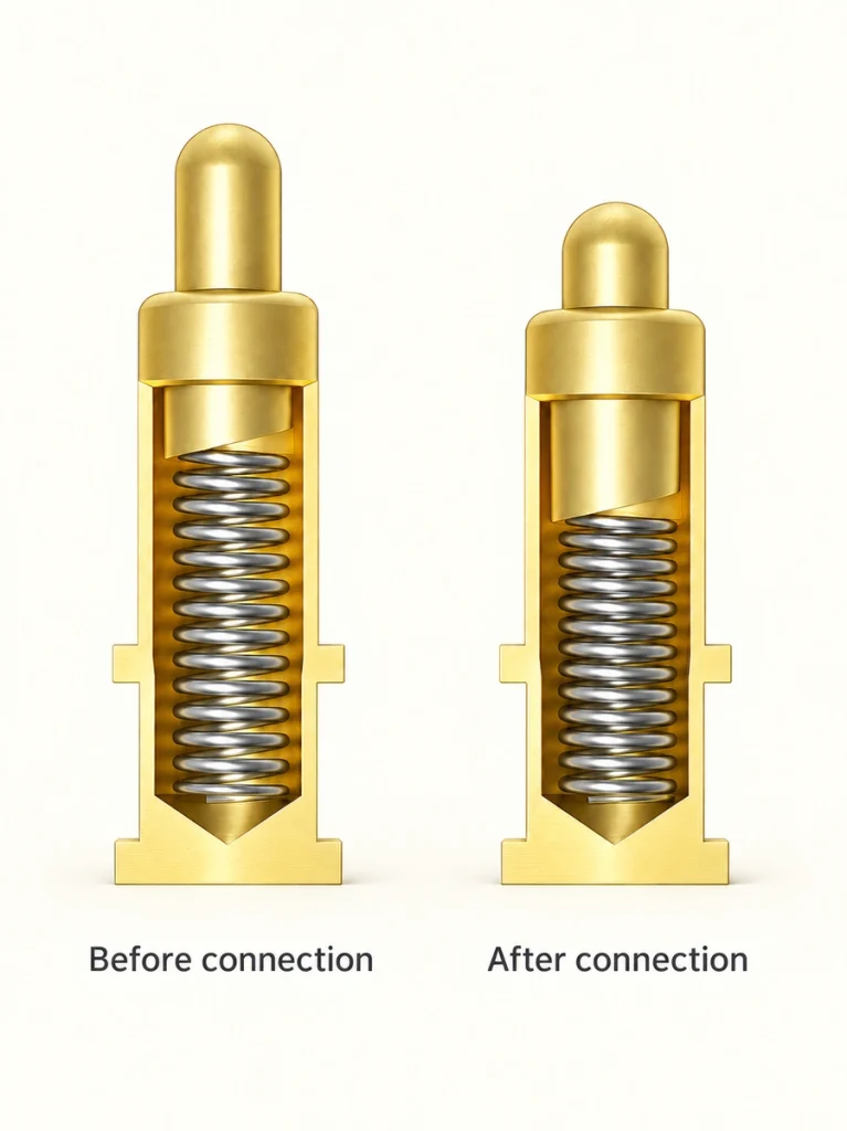
At the seated position, the spring contacts compress against the pads within their specified working range.
The travel accommodates limited axial dimensional variation while maintaining pressure. Contact height, stop position and lateral alignment still need to stay within the design limits.
For an OEM product, that mechanism can be integrated directly into the device instead of adding a retail adapter to an existing port.
An adapter arrangement is:
Existing USB-C port → compatible detachable magnetic tip
An integrated alternative is:
Device PCB → custom spring-contact interface ↔ matching magnetic cable → suitable USB-A or USB-C termination
A dedicated device-side interface can avoid a conventional receptacle and fit the enclosure. It does not bypass the required charging controls, source detection or applicable USB requirements.
Custom-cable inputs for OEM products
A retail adapter can be convenient where an existing USB port and the cable system are compatible.
An OEM design may instead need control over:
Connector dimensions
Number of contacts
Pin pitch
Power and signal allocation
Current capacity
Magnetic force
Working height
Cable length
90° or 180° cable direction
USB-A or USB-C cable termination
Waterproof sealing
PCB mounting method
PCB
A custom contact pair and cable can be worth evaluating when those requirements cannot be met by an adapter. Confirm feasibility and performance for the proposed assembly.
Wearables, medical equipment, smart-home products, handheld terminals and docks can impose tight enclosure constraints. Design the interface around the actual packaging and product requirements without implying qualification for every application.
From an adapter to an integrated interface
Many detachable magnetic cables and custom spring-contact designs share these elements:
Magnetic guidance; conductive mating surfaces; a separable joint
Their integration into the product differs.
A retail magnetic cable adapts an existing plug interface. An OEM assembly can instead form part of the original electrical and mechanical architecture, with its own mating requirements.
Coordinate PCB position, enclosure, charging current, signals, seal structure and cable routing in that integrated design.
Magtor develops magnetic spring-contact pairs and cable assemblies for charging, power and defined signals or data. USB-A, USB-C or other terminations, contact counts and cable exits can be considered. Straight and 90° or 180° cable arrangements describe geometry, not universal protocol capability or reversed electrical mating.
magnetic spring-contact pairsMagtorWhere an existing cable does not fit the envelope, electrical needs, seals or PCB layout, discuss a custom interface and its validation requirements.
Explore Magtor magnetic-interface designs or contact the engineering team with your device requirements for a custom cable review.
Conclusion
Magnetic USB cables engage a compatible cable head and device-side tip through magnetic guidance. Correctly seated contacts then carry power and the signals implemented by that combination.
The magnetic joint is a removable physical connection, distinct from contactless inductive charging.
A compatible detachable tip can adapt an existing consumer-device port. A custom spring-contact design can instead address OEM needs for packaging, pin allocation, sealing, combined signals and specialised routing, with the complete electrical requirements validated.
Consider a custom interface when the actual device requirements exceed the capabilities or fit of the available cable system.