
Higher-current Magnetic Connectors: Design, Maintenance and Selection
Published on July 22, 2026
- Defining a Higher-current Magnetic Interface
- How the Power Connection Works
- Potential Benefits and Trade-offs
- Maintaining the Connection
- Understanding Price and Cost
- Features to Compare
- Specification and Purchasing Checks
Higher-current magnetic interfaces can simplify repeated docking where the power path, retention and release behavior are designed for the device. This guide explains their construction, candidate applications, maintenance and purchasing checks. Verify electrical loading, temperature rise and exposure conditions before treating a configuration as suitable for your product.
Higher-current magnetic interfaceDefining a Higher-current Magnetic Interface
A higher-current magnetic interface uses magnets to guide and retain mating parts while conductive contacts carry the load. A broad design example spans 5–30A or above, depending on the contact architecture and qualified conditions; this is not a rating for every spring-contact design or a Magtor product promise above 30A. Some assemblies also provide signal paths, shielding or environmental seals.
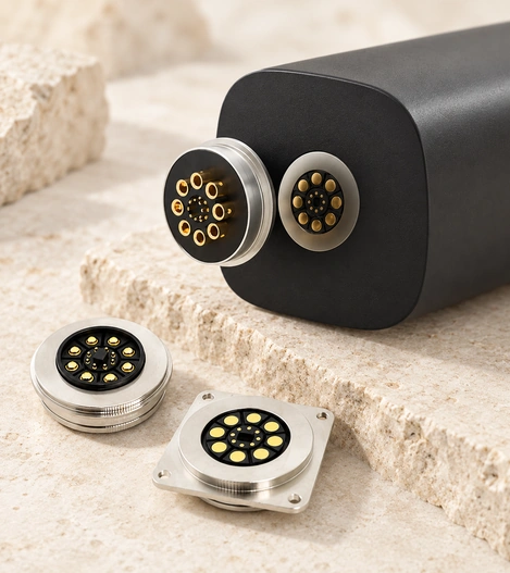
Scope and Candidate Applications
Consider this approach when frequent connection, quick docking or controlled release is needed alongside a suitable power path. Any safety benefit of release must be assessed in the complete device.
Application patterns include:
Docking and charging for e-bikes, scooters, AGVs, robots, medical carts and industrial handheld devices.
Modular power packs, including battery modules intended for hot swapping and portable energy storage; hot swapping requires appropriate circuitry and sequencing.
High-use or demanding environments involving dirt-prone workstations, vibration or repeated handling.
Equipment where a controlled cable release may reduce damage from a trip or pull, subject to product-level safety evaluation.
Define the requirement using current, duty cycle, allowable temperature rise, available space and operating environment together. An ampere value alone is not enough to describe a usable connector rating.
| Illustrative category | Example current range | Example use | Design considerations |
|---|---|---|---|
| Medium power | 5–15A | Powered docks and tools | Compact packaging may be possible; verify thermal performance |
| Higher power | 15–40A across suitable connector architectures | Light electric-mobility or robot docks | May require larger contacts and more heat dissipation; values above 30A are not a confirmed rating of our spring-contact range |
Scroll horizontally to view every column.
Design guidance: 30A is the upper target discussed here for our higher-current spring-contact designs, subject to verification. Ordinary contact examples at 5A or below do not define a universal limit. For requirements of 50A or 100A, assess an alternative power-contact architecture rather than extrapolating a pogo-contact rating.
How the Power Connection Works
Magnets draw the mating parts toward the intended position, and the contact geometry and spring travel establish the conductive connection. Retention and guidance come from the magnetic and mechanical arrangement; the current flows through the metal contacts, pads and terminations. Verify pressure and resistance under the actual applied loads.
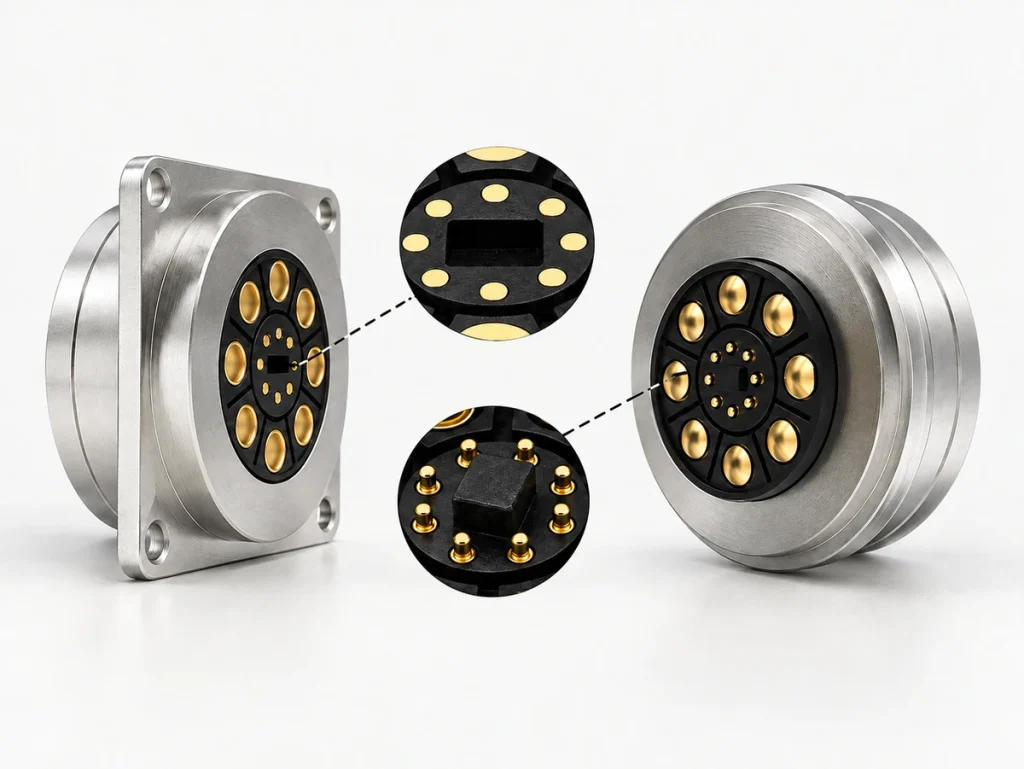
Magnetic Guidance and the Conductive Path
Magnetic parts primarily guide and hold the assembly. Electrical performance depends on the contact system, thermal path and mechanical stability.
A typical connection sequence is:
Approach and capture: attraction guides the mating half within the designed capture range.
Alignment: keys, chamfers and pole placement position the contacts for correct overlap.
Contact engagement: spring force and the mating geometry establish the specified pressure.
Power transfer: current passes through the conductive interface, with resistance affecting voltage drop and heating.
Release: the magnetic retention separates under the designed pull; verify the release load and resulting device behavior rather than assuming damage-free disconnection.
Variables to evaluate for higher-current operation include:
Contact resistance in milliohms: changes affect I²R heating at a given current.
Resistance of the contact pathContact area and pressure: stability helps limit interruptions, oxidation effects and arcing risk under the specified conditions.
Plating: gold, silver or tin may be considered according to contact function, environment and cycle target; there is no universal signal-versus-power finish rule.
Contact finishThermal path: housing materials, copper mass and mounting influence temperature rise.
Life guidance: pad-facing spring contacts can reduce insertion-related sliding, but still experience wear. Tens of thousands of cycles, or hundreds of thousands for some specially qualified designs, are example targets that need a defined test method, load and exposure profile.
Potential Benefits and Trade-offs
A suitable magnetic design may improve docking convenience and reduce damage caused by forced insertion. Controlled release and quicker charging or power-pack replacement may also be useful, provided the device’s safety and sequencing requirements are addressed. Confirm resistance and contact-force stability after the required life tests.
Benefits to Evaluate in the Product
Potential design benefits include:
Quick docking within the specified alignment range.
Lower risk of bent contacts or incorrect mating where locating features are effective.
Controlled release under a specified excessive pull, with the device’s safety requirements verified.
Easier attachment for gloved hands or low-visibility use.
Long mating-life potential from an optimized contact system, assessed against a specific alternative and test method.
Account for these trade-offs when evaluating those benefits:
Magnets can attract ferrous debris.
An inadequately sized or unstable contact path can overheat.
Exposed contacts may need safeguards against short circuits and contamination.
Design guidance: grinding or machining environments can introduce conductive metal dust. Assess recessed contacts, an appropriate wiping geometry and a cleaning plan so that attracted debris does not bridge conductors or increase resistance. These measures need verification in the actual environment.
Maintaining the Connection
Keep the contact surfaces clean, inspect for wear and heat discoloration, and check that the assembly remains securely mounted. Use cleaning methods approved for its plating, plastics and seals. Under a controlled and safe test procedure, trend voltage drop or temperature rise at a known load to identify deterioration.
Maintenance Checks for Contact and Thermal Health
A repeatable inspection sequence is:
Switch off and isolate power before handling the connection.
Inspect for pitting, darkened areas, softened or melted plastic, and loose fasteners.
Remove debris using approved non-metallic tools or controlled compressed air; avoid steel brushes.
Clean with an approved solvent and lint-free swabs. Isopropyl alcohol is suitable only where the materials permit it; do not abrasively polish away plating.
Isopropyl alcoholCheck magnet fixation, retention and consistent seating of the housings.
Under an approved electrical test procedure, measure voltage drop at a known load and compare the trend over time.
Measured voltage drop
Possible starting intervals for a maintenance plan are:
High-cycle docks: weekly to monthly.
Dusty industrial sites: weekly.
Clean indoor charging equipment: quarterly to every six months.
Test guidance: low-resistance measurements can be affected by leads and contact setup. A repeatable voltage-drop test at the same controlled current and duration can help track degradation. Select the measurement method and safety procedure for the assembly rather than treating one method as universally better.
Understanding Price and Cost
Cost depends on current requirements, contact count, plating, seals, materials and the required compliance work. An illustrative early-budget scenario might place a basic off-the-shelf pair in the tens of dollars, with sealed, high-cycle or custom high-current sets costing more at low volume. This is an unverified planning example, not current pricing or a quotation; request a configuration- and quantity-specific offer.
Main Unit-cost Drivers
Items that may affect the quotation include:
Current and thermal requirements: copper mass, contact size and housing design.
Contact system and finish: silver, tin or gold as appropriate, and plating thickness for the required life.
Environmental seals: gaskets, overmolding and the testing needed for targets such as IP67 or IP68.
Ingress-protection ratingMagnet material and retention design for temperature and shock conditions.
Cable assembly: conductor gauge, strain relief, overmolding and termination labor.
Required compliance work: applicable UL or IEC requirements, transport conditions and reliability documentation; not an assertion that every design holds these approvals.
Applicable UL requirementsApplicable IEC requirements
For early budgeting, compare the following configuration factors.
| Configuration | Relative cost pressure | Reason to assess |
|---|---|---|
| Standard unsealed power-only assembly | Often lower | Fewer components and simpler molding |
| Power, signals and shielding | Often intermediate | Extra contacts and tolerance requirements |
| Higher-IP sealed assembly with a long cycle target | Often higher | Sealing tolerances, validation and quality controls |
| Custom mechanics with required compliance work | Potentially highest | Tooling, testing and documentation |
Scroll horizontally to view every column.
Budget guidance: quote the connector pair and cable assembly separately when useful. Conductor gauge, overmold tooling and strain relief can materially affect the total, even where the magnetic mating interface is unchanged.
Features to Compare
Compare current capacity, thermal performance, resistance stability, mating life and environmental protection under matching conditions. Two assemblies with the same headline current value may differ in continuous operation, peak duration, mounting or heat dissipation. Include contamination and alignment checks representative of the product.
Feature-by-feature Specification Checks
The following engineering comparison is a selection aid; it does not present verified internal test results or a market-ranking study.
| Feature | Why it matters | Specification items | Pitfall to avoid |
|---|---|---|---|
| Continuous current | Controls sustained heating | Current, ambient temperature and allowable temperature rise (ΔT) | Providing only a peak-current value |
| Resistance stability | Affects I²R heating and reliability | Initial milliohm resistance and values after life testing | Ignoring resistance after wear |
| Contact construction: pins, pads or springs | Controls wiping, pressure and tolerance accommodation | Geometry and contact force | Insufficient or unstable engagement increasing interruption or arcing risk |
| Plating system | Affects corrosion and wear performance | Material and thickness | Using a finish unsuitable for the exposure |
| Magnetic retention and alignment | Affects mating and vibration stability | Retention force and keying | Treating the magnets as adequate support for every external load |
| IP sealing | Addresses specified dust and water exposure | Rating, test method and protected assembly state | Claiming protection without validation |
| Thermal path | Supports sustained power transfer | Mounting and heat-dissipation requirements | Ignoring the enclosure’s restricted airflow |
| Fault and short-circuit protection | Helps address fault risks | Recessing, sequencing and circuit protection as required | Leaving accessible contacts unprotected against conductive debris |
Scroll horizontally to view every column.
Rating guidance: require the mounting arrangement, airflow, ambient conditions and duty cycle behind the stated current. Without those conditions, the value cannot be reliably applied to a different enclosure.
Specification and Purchasing Checks
Assess electrical performance, operating environment, service life and supply requirements before comparing quotations. A lower unit price is useful only if the assembly meets the continuous-load and temperature limits, required life and mechanical needs. Include likely servicing and failure costs in the decision.
Define Requirements Before Optimizing Cost
Document this shortlist when requesting a configuration:
Electrical: continuous and peak current, voltage, allowable voltage drop and duty cycle.
Thermal: maximum connector temperature, ambient range, enclosure airflow and nearby heat sources.
Mechanical: mating cycles, retention, allowable side load, vibration and shock.
Environment: IP target, metallic or non-metallic dust, salt fog, chemicals and UV exposure.
Integration: panel or cable mounting, keying, incorrect-mating protection, strain relief and conductor gauge.
Safety: accessible-contact protection, controlled release and any required sequencing, including signal-before-power where appropriate.
Quality and documentation: test reports, traceability and incoming inspection requirements.
Potential ways to reduce total cost include:
Use fewer compatible variants where one footprint can serve different cable lengths.
Match plating and sealing to the defined environment instead of adding unsupported requirements.
Perform representative thermal and voltage-drop checks early to identify changes before tooling or volume production.
Cost guidance: have engineers define accurate electrical and mechanical requirements from the real application. A justified specification is more useful than increasing every performance target without a product need.
Design Summary
A magnetic interface may suit repeated power docking where guided attachment and controlled release are useful. Treat current as a complete contact-resistance and thermal-design requirement, then select plating, sealing and mechanics for the exposure and life target. Share those conditions with Magtor so that a suitable configuration and validation plan can be assessed.
Magtor