
Choosing Between Contact and Wireless Charging
Published on September 4, 2026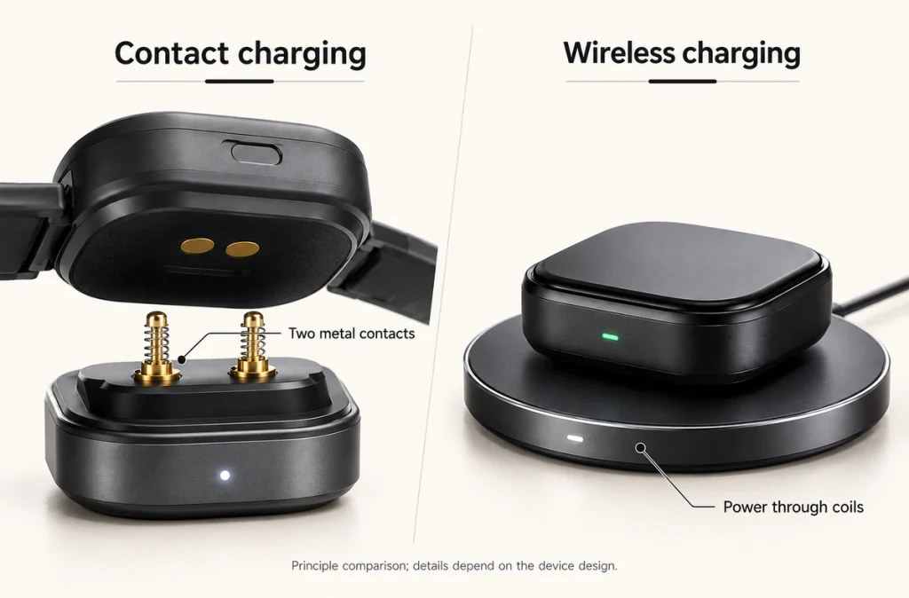
- Conductive and Inductive Power Transfer
- The Contact Charging Path
- The Wireless Charging Path
- Efficiency, Heat and Packaging
- Sealing, Wear and Reliability
- Selecting a Charging Architecture
Contact charging conducts power through components such as pogo pins and pads. The wireless charging discussed here uses electromagnetic induction instead. Compare efficiency, heat, sealing, device size, contact wear, alignment and signal needs before choosing an architecture.
Conductive and Inductive Power Transfer
The distinction is the route across the interface: contact charging uses a conductive connection, while inductive charging couples energy through electromagnetic fields across a small gap or insulating enclosure surface.
| Feature | Contact charging | Inductive wireless charging |
|---|---|---|
| Power transfer | Conductive contacts | Electromagnetic induction |
| Typical interface | Pogo pins and pads | Transmitter and receiver coils |
| Physical electrical contact | Yes | No |
| Contact wear | Possible | No conductive mating wear |
| Power and additional application signals | Possible with assigned contacts | Application signals usually need another interface |
| Alignment | Mechanical or magnetic guidance | Coil alignment |
| Exposed contacts | Usually present | Not required |
| Compact interface | Often very compact | Depends on coils and electronics |
Scroll horizontally to view every column.
Contact charging covers several interface types. Magnetic pogo pin charging is one: magnets position the parts, and conductive contacts carry the power.
The Contact Charging Path
A typical conductive system has this power route:
Power source → charging contacts → mating pads → device charging circuit → battery.
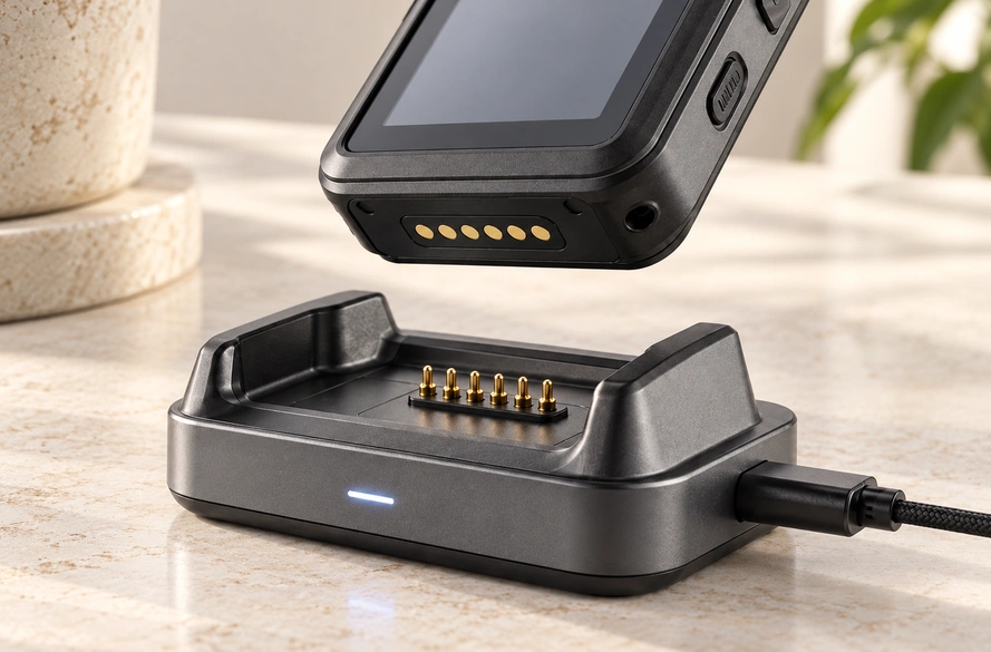
Magnets can guide and retain the device while pogo pins establish the electrical connection. The Magtor guides How Do Magnetic Charging Connectors Work? and How Does a Charging Dock Work? explain these roles in more detail.
How Do Magnetic Charging Connectors Work?Charging Dock GuideThe Wireless Charging Path
An inductive charger needs no exposed conductive connection to the device. Its transmitter coil produces an alternating field that couples energy into a receiver coil inside the device.
The simplified energy route is:
Power source → transmitter coil → electromagnetic field → receiver coil → charging electronics → battery.
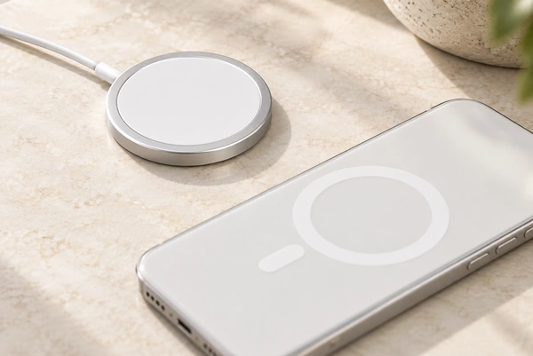
Qi is a consumer wireless charging standard developed by the Wireless Power Consortium. Qi2 includes magnetic alignment of transmitter and receiver coils. The WPC Qi Wireless Charging overview describes the standard ecosystem.
Wireless Power Consortium – Qi Wireless ChargingMagnetic alignment can therefore appear in two different arrangements:
Magnetic contact charging: magnets align the parts, and metal contacts conduct power. Magnetic inductive charging: magnets align the coils, and electromagnetic coupling transfers energy.
The presence of magnets alone does not make a charger wireless.
Efficiency, Heat and Packaging
Conductive charging avoids a coil-to-coil transfer stage. Current, contact resistance, pin compression, plating, conductor size, PCB layout and contamination influence heating. Rising resistance can increase voltage drop and I²R losses; the magnetic connector heating guide discusses this relationship.
Why Does a Magnetic Connector Get Hot?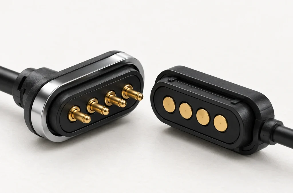
Inductive performance depends on coil alignment, spacing, power electronics and thermal design. Qi systems combine alignment and power management, but their mechanical and electrical architecture differs from a direct conductive interface.
For a small device, a few spring contacts and pads can make the external interface compact. Inductive charging needs a receiver coil and its electronics; the actual space trade-off must be assessed within the device.
Sealing, Wear and Reliability
Inductive charging can simplify a sealed outer surface by removing exposed conductive charging contacts. It avoids wear at that conductive mating interface, though it does not remove all mechanical wear or establish the enclosure's water protection.
Exposed conductive contacts may encounter sweat, moisture, dust, skin oils, oxidation and wear. Select materials, plating and protection for those conditions. A suitable pogo pin design can support repeated docking and provide assigned paths for power, signals, ID or detection.
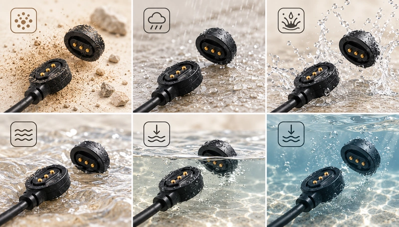
For frequent mating or sweat exposure, choose plating for the environment and target service life. The Magtor Pogo Pin Gold Plating guide considers gold thickness, wear, corrosion, force and mating surfaces in long-term contact reliability.
Pogo Pin Gold Plating: Thickness, Wear & CorrosionSelecting a Charging Architecture
Consider contact charging for a compact conductive interface, frequent docking, direct power, additional signal or detection contacts, or custom assignments. Earbuds, wearables, medical electronics, handheld terminals and docks are application examples.
Consider inductive charging when avoiding exposed contacts, retaining a sealed exterior, or participating in a compatible wireless ecosystem such as Qi is a priority. Ecosystem compatibility still depends on the implemented system.
A magnetic contact interface is an option where direct conduction and guided alignment are both needed. Its spring contacts and magnets can be designed around contact count, current, working stroke, retention force and available space.
Magtor Magnetic Connector solutions can be assessed for OEM power, charging and signal interfaces where standard arrangements do not fit the product's mechanical layout.
Magnetic Connector solutionsMatching the Architecture to the Product
A conductive interface can suit compact, frequently docked equipment that also needs detection or signals. An inductive system removes the conductive mating surface and can suit sealed, contactless designs. Each approach addresses a different set of requirements.
Assess size, current, heat, environmental exposure, mating frequency, charging speed, data needs and mechanical structure together. No charging technology is universally the better choice.
For compact OEM electronics, magnetic guidance with pogo contacts offers another architecture: magnets assist alignment while the physical contacts create a direct power path.