
Magnetic Connector Faults: Causes and Practical Checks
Published on May 28, 2026
- Magnetic Connector Construction
- Connector Types and Typical Failure Causes
- How Contact Is Made and Why It Can Become Unstable
- Benefits and Their Design Trade-offs
- Maintaining Magnetic Contacts
- What Determines Connector Price
- Purchasing Checks That Reduce Failure Risk
Magnetic mating makes connection easier, but contamination, reduced holding force, misalignment, corrosion, unintended release and high-current heating can still cause faults. Evaluating these mechanisms alongside the application requirements helps improve the connector’s performance over its service life.
Magnetic Connector Construction
A typical magnetic interface combines a plastic housing, magnets and spring-loaded contacts. Magnetic attraction aligns and retains the halves, while the contacts carry electrical power or signals. Some designs supply power alone; others use additional pins for power and data. Current capacity, sealing and durability must be checked for the particular connector rather than inferred from magnetic mating alone.
Magnetic connector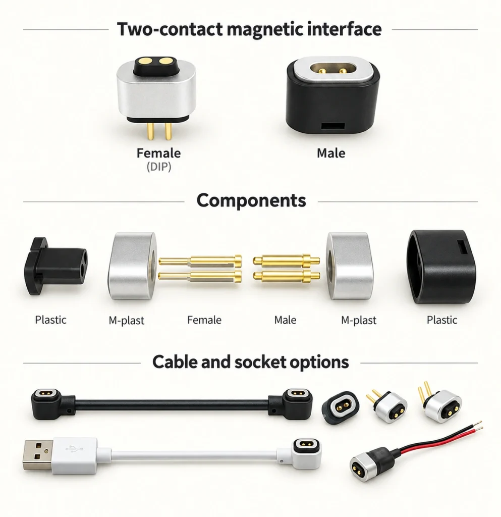
Connector Types and Typical Failure Causes
The design brings together magnetic retention, an electrical contact system and magnetic alignment. A connection fault can result when these features are not suited to the operating environment, even if the individual components meet their own specifications.
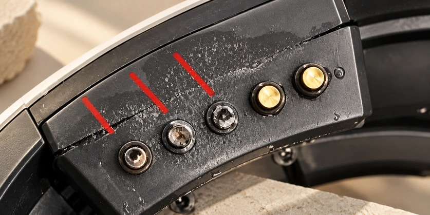
Male pogo contacts — spring travel can accommodate some movement, but debris and worn plating can disrupt contact.
Pogo-pin contactFemale copper posts or pads — recessed areas can collect foreign material that prevents full engagement.
Magnets — exposed magnets can be damaged by impact; excessive attraction combined with inadequate mounting can pull a magnet from its seat.
| Arrangement | Typical function | Failure conditions to consider |
|---|---|---|
| 1pin–2 pin | Simple current or signal paths within a complete circuit | Sweat or workplace chemicals |
| Multiple pins | Power, signals, data and other assigned functions | Contact wear and corrosion |
| High-current connector | Tools, robots and battery packs | Excess current or resistance-related heating |
Scroll horizontally to view every column.
Selection note: first define whether the interface carries power only or power and data, whether it operates indoors or outdoors, and the required current. Choose its geometry and sealing from those requirements. Investigate a specification mismatch as well as a possible manufacturing defect when diagnosing a fault.
How Contact Is Made and Why It Can Become Unstable
Magnets guide alignment and retain the joint; pogo pins form the electrical contact. This can reduce insertion effort and wear, but stable operation still depends on the contact dimensions, plating and mechanical structure, which influence resistance, heat and signal transfer.
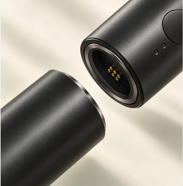
The Electrical Path and Intermittent Faults
Mating generally follows approach, magnetic capture, mechanical alignment, contact compression and current flow. Surface contamination or lateral loading can increase contact resistance or interrupt contact, producing an unstable charging or signal connection.
Magnetic capture — rapid engagement can stress the contacts if the mating tolerances are unsuitable.
Alignment features — pins, rails or housing geometry help prevent reversed polarity and reduce positional error.
Contact engagement — pogo spring force or pressure on a flat pad affects the consistency of contact resistance.
Current transfer — increased resistance produces more heat for a given current.
Plating — an unsuitable coating system can corrode in a harsh environment.
Lateral mating load — side friction and incorrect alignment can damage the contact components or pin barrel; account for these loads in the mating geometry.
| Stage | Possible fault mechanism | Observable symptom |
|---|---|---|
| Alignment | Lateral loading or offset | Intermittent charging |
| Contact | Oxide or debris on the surface | Slow charging or a warm connector |
| Loaded connection | Arcing during disconnection under load | Pitting, dark marks or early contact failure |
Scroll horizontally to view every column.
Design note: review the connector’s structure and performance against the equipment’s actual use. A mating geometry that does not fit the device or its loading conditions can undermine an otherwise suitable electrical specification.
Benefits and Their Design Trade-offs
Magnetic mating can be quick and intuitive, reduce sliding wear relative to a friction-fit plug and provide planned release when a cable is pulled. It can also be integrated into a sealed interface or blind-mating dock. A compact 2-pin arrangement is particularly useful where a small device has little space or weight allowance for its charging connection.
Practical Advantages and the Conditions Behind Them
A magnetic interface can be an appropriate choice when easy handling is a primary product goal. Its convenience should be assessed alongside electrical compatibility, retention and the operating environment.
Easy docking — magnetic alignment can reduce insertion mistakes.
Planned breakaway — a specified release behavior can limit the load passed to the PCB or port during a cable pull.
Lower mating wear — fewer forceful insertions can benefit a frequently docked product.
Flexible integration — recessed charging points and sealed housings can be designed around the interface.
Configuration range — arrangements can extend from a single contact within a complete circuit to hundreds of contacts, or to a specifically engineered 30A high-current interface; capability depends on the selected design.
high-current magnetic connector
| Benefit | Possible use | Design constraint |
|---|---|---|
| Self-alignment | Blind docking | Mechanical stops are needed to control offset |
| Breakaway behavior | Protection against a pull or drop | Unsuitable when the application requires retention above the release threshold |
| Long mating life | 10,000–100,000 docking cycles as design-dependent examples | Contact plating, cleanliness and the actual cycle-test conditions are critical |
Scroll horizontally to view every column.
Engineering note: magnets provide alignment and retention assistance. The mechanical datum surfaces and contact system must still satisfy the application’s electrical and mechanical performance requirements.
Maintaining Magnetic Contacts
Keep the contact area clean and protect it against corrosion. Inspect for debris, worn plating and heat discoloration when investigating intermittent power. Cleaning can restore a contaminated interface, while harsh-environment failures may require a more detailed investigation and suitable measurement equipment. Damaged contacts need evaluation rather than repeated cleaning alone.
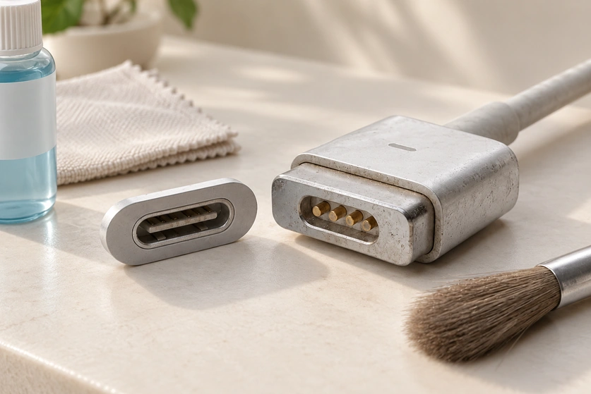
A Routine for Common Failure Mechanisms
Maintenance should address contamination, oxidation or corrosion, and contact wear. Select the cleaning method and inspection interval for the materials and conditions of the actual assembly.
Switch power off before cleaning or intentional removal to avoid disconnecting a loaded contact.
Remove loose debris first with permitted compressed air or a clean swab that does not shed lint.
Where material-compatible, apply a small amount of IPA (isopropyl alcohol) with a swab and allow the contact area to dry completely.
IPA (isopropyl alcohol)Inspect mating surfaces for pits, dark carbon marks and uneven wear.
Investigate abnormal temperature, discoloration or softened plastic; these can indicate increased resistance. Do not handle a dangerously hot powered connection.
Check the mounting and alignment features, because loose hardware can allow small movements and intermittent contact.
Troubleshooting note: inspect damage caused by incorrect mating orientation as well as corrosion or pin damage associated with the operating environment. These checks help distinguish a mechanical or environmental fault from another electrical problem.
What Determines Connector Price
Pin count, current rating, contact plating, magnet type, required cycle life and sealing all affect cost. A basic 2-pin consumer charging interface generally has fewer requirements than a sealed high-current assembly for harsh service. Custom tooling, nonstandard structures and required compliance or validation work also influence the complete quotation.
2-pin magnetic connectorConfiguration and Cost Drivers
The following table compares typical configuration and cost considerations. It is a qualitative purchasing guide, not a fixed price list or a verified internal cost dataset.
| Category | Example configuration | Principal cost drivers | Relative cost considerations |
|---|---|---|---|
| Entry level | 1–2 pins without sealing | Basic plating and less demanding tolerances | Usually the lowest unit cost in this comparison; contamination risk needs attention |
| Mid range | 2–6 pins with improved alignment | Plating thickness and spring quality | Moderate cost with the goal of stable docking |
| High reliability | A sealed, IP-rated design | Gaskets, precise housings and validation | Higher cost to meet the defined reliability requirements |
| High-current connector | Larger contacts and a designed thermal path | Copper volume, low-resistance contacts and testing | Typically the highest cost in this comparison; heat and arcing still need control |
Scroll horizontally to view every column.
Quotation note: a useful price comparison needs the application environment and the performance specification. Supplying those details allows the manufacturer to quote an interface suited to the intended use.
Purchasing Checks That Reduce Failure Risk
Current margin, thermal performance, alignment tolerance and environmental sealing should guide purchasing decisions. Pin count and magnetic strength alone do not establish whether a connector will remain reliable in the application.
A Checklist for Selecting the Interface
Electrical margin — select the rating for both peak and steady-state requirements and verify the resulting temperature rise.
Loaded mating — establish whether connection or removal occurs under load, and provide load switching when the system requires it.
Environment — account for dust, sweat, salt fog, cleaning chemicals and metal particles.
Mechanical alignment — specify polarity protection and hard stops instead of depending on magnets alone.
Cycle-life evidence — request mating-cycle results and contact-resistance measurements after cycling.
Safety and compliance — review insulation, applicable creepage and clearance requirements, and material flammability ratings.
Electrical note: specify the peak-current waveform as well as average current. A brief high-current demand can make a contact run hot or arc even when an average-current figure appears acceptable. Evaluate the actual waveform and mating conditions.
Reducing Connector Faults
Contamination can raise resistance, incorrect alignment can interrupt contact, corrosion can damage the plating, and removal under load can produce arcing. These mechanisms deserve particular attention in high-current applications. Appropriate mechanical alignment, power control and a compatible inspection and cleaning routine help manage them. Magtor can review the load, environment and service-life targets when recommending a connector configuration.