
Magnetic Connector Contact Types: Six Structures Explained
Published on June 23, 2026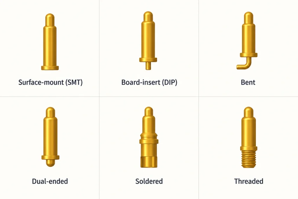
- Why Contact Termination Matters
- 1. Surface-mount Contacts
- 2. Through-hole Contacts
- 3. Bent Contacts
- 4. Double-ended Contacts
- 5. Wire-solder Contacts
- 6. Threaded Contacts
- Comparing the Six Structures
- Choosing a Structure for the Assembly
- Custom Contact Requirements
Contact count defines how many paths are available, while contact type affects how those paths connect to the PCB or cable. This guide compares surface-mount, through-hole, bent, double-ended, wire-solder and threaded structures. Use the differences in assembly, support and integration to select a design that can meet the required electrical and mechanical performance.
Why Contact Termination Matters
The contact termination links the magnetic assembly to its PCB or cable. Its geometry and mounting method affect:
magnetic connectorThe assembly process.
Mechanical support.
Solder-joint reliability.
Current-carrying performance.
Vibration behavior.
Maintenance access.
Manufacturing cost.
A suitable contact structure can simplify production while supporting the intended service requirements, provided the complete assembly is validated.
1. Surface-mount Contacts
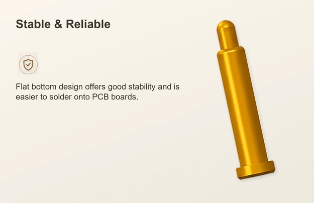
An SMT contact solders to a pad on the PCB surface rather than passing through a mounting hole. With an appropriate footprint and process profile, it can fit an automated SMT line and a compact electronic assembly.
Application Examples
Smartphones.
Smartwatches.
True-wireless stereo earbuds.
Tablets.
Wearable devices.
Other consumer electronics.
Potential Advantages
Compatibility with an appropriate automated SMT process.
A footprint suited to dense PCB layouts.
Potentially lower assembly cost in volume production.
An option for miniature products.
Integration into a rapid assembly workflow.
Constraints to Review
Solder-pad retention may be lower than a suitably supported through-hole arrangement.
External operating forces need a support review rather than being carried by pads alone.
Pad geometry and the solder process must provide adequate joint strength.
2. Through-hole Contacts
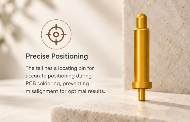
A through-hole or board-insert contact passes through a PCB hole and is soldered as specified by the process. This structure can provide additional mechanical anchorage, although the final strength depends on the board, joints and housing support.
Application Examples
Industrial equipment.
Medical devices.
Automotive electronics.
Charging docks.
Appropriate higher-current interfaces.
Potential Advantages
A strong mechanical anchorage option.
Support for vibration and shock requirements when validated.
An option for larger connector structures.
A mounting arrangement that can support a demanding service-life target.
A possible current-path design for higher-current requirements, with thermal validation.
Constraints to Review
The PCB needs the specified through holes.
Assembly may take longer than the chosen SMT process.
The manufacturing process may add cost.
3. Bent Contacts
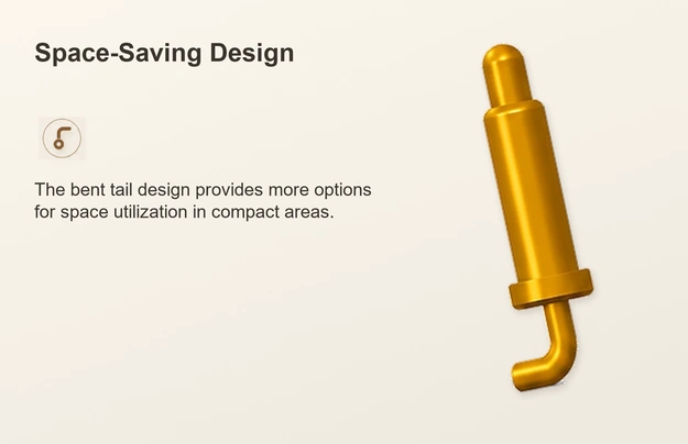
A bent contact may use a 90° bend or another specified angle. The arrangement lets the mating interface sit parallel or perpendicular to the PCB as required by the product geometry.
Application Examples
Slim electronic products.
Side-entry interfaces.
Charging cradles.
Compact docking stations.
Potential Advantages
More options for mounting orientation.
Efficient use of internal space.
A contact arrangement that can simplify enclosure integration.
A layout suited to the required cable routing.
Constraints to Review
Bending and dimensional control add manufacturing steps.
Installation loads and stress at the bend require review.
4. Double-ended Contacts
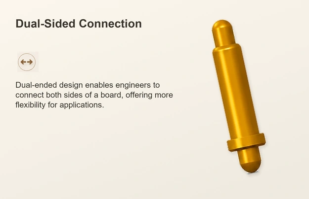
A double-ended pogo contact has a compressible plunger at each end. Both mating sides can move through their specified working travel to establish electrical engagement.
Application Examples
Docking stations.
Modular equipment.
Battery packs.
Internal board-to-board connections.
Custom industrial assemblies.
Potential Advantages
Electrical engagement at both ends.
A possible reduction in separate wiring.
An option for modular construction.
Assembly simplification where the locating structure supports it.
Constraints to Review
Both mating ends require suitable dimensional control.
The contact and supporting structure are more complex.
5. Wire-solder Contacts
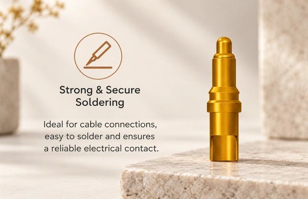
A wire-solder termination accepts a conductor directly rather than mounting on a PCB pad. Depending on the process, wires may be soldered manually or with suitable automation to the specified terminal geometry.
Application Examples
Cable assemblies.
Custom wire harnesses.
Medical equipment.
Industrial sensors.
Portable devices.
Potential Advantages
Flexible conductor routing.
Application-specific wiring options.
A practical approach for some lower-volume assemblies.
A choice of conductor gauges within the termination’s limits.
Constraints to Review
Manual assembly can require substantial labor.
Solder quality and strain relief affect reliability.
The process may be less suited to high-speed automated production than the selected PCB process.
6. Threaded Contacts
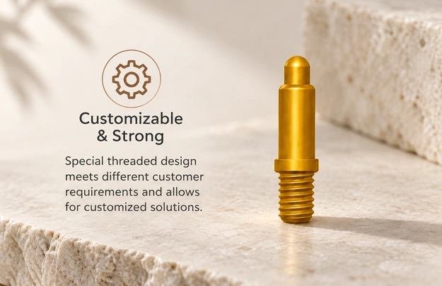
A threaded contact uses an internal or external thread for mechanical retention in a screw or threaded housing arrangement. Follow the specified mounting geometry and installation process for the selected part.
Application Examples
Industrial automation.
Robotics.
Outdoor equipment.
Aerospace equipment with the required qualification.
Heavy-duty interface structures.
Potential Advantages
A mechanically secure fastening option.
A structure that can meet specified vibration requirements when properly installed.
Resistance to loosening through the approved fastening arrangement.
An option for demanding environments with suitable materials and sealing.
Access for repeated maintenance where the structure permits it.
Constraints to Review
Additional installation space may be needed.
Thread machining can add cost.
Fastening can increase assembly time.
Comparing the Six Structures
| Contact type | Mounting arrangement | Indicative mechanical support | Automation potential | Application example |
|---|---|---|---|---|
| Surface-mount (SMT) | PCB surface pads | Medium in the source comparison; verify the supported assembly | High with a suitable SMT process | Consumer electronics |
| Board-insert / through-hole | Through-hole PCB | High in the source comparison; verify board and joints | Moderate, depending on the process | Industrial and automotive equipment |
| Bent | Right-angle arrangement | Good in the source comparison; verify loads at the bend | Good, depending on the process | Compact electronics |
| Double-ended | Contact at both ends | Good in the source comparison; verify the locating structure | Moderate, depending on the assembly | Modular equipment |
| Wire-solder | Soldered conductors | Depends on joint quality and support | Lower in the source comparison; automation options vary | Cable assemblies |
| Threaded | Threaded fastening | High in the source comparison; verify installation | Lower in the source comparison; fastening process varies | Industrial equipment |
Scroll horizontally to view every column.
Choosing a Structure for the Assembly
Select the contact type by reviewing the product and manufacturing requirements together.
PCB Assembly Process
An automated SMT line favors a compatible surface-mount termination.
Through-hole contacts may suit a specified wave-soldering or manual-soldering process.
Mechanical Requirements
Through-hole anchorage or threaded fastening may be useful where vibration or repeated mating loads are demanding. Evaluate housing support and qualification loads before selecting the structure.
Available Space
SMT or bent contacts can help use limited PCB and enclosure space, depending on the required mating direction and support.
Electrical Load
A higher-current interface may use larger through-hole or threaded contact structures. Confirm temperature rise and the complete current path; the termination category alone does not establish current capacity.
Production Cost
A suitable SMT process can reduce assembly cost at volume, while custom threads or double-ended structures may add complexity. Compare actual part, tooling and process quotations rather than assuming one type is always cheapest.
Custom Contact Requirements
Ask the supplier which contact parameters can be customized for the intended application, including:
Contact length.
Contact diameter.
Mating-face shape.
Contact spacing or pitch.
Mounting orientation.
Thread specification.
Wire-termination style.
Verified current rating.
Gold-plating thickness.
A custom contact can improve fit between the electrical paths and assembly process, provided the revised structure is manufacturable and validated.
Contact-selection Questions
Which Requirements Determine the Contact Structure?
Define power, communication paths, available space, exposure and possible future expansion before choosing a structure. Then compare assembly methods and validate the complete interface against those requirements.
When Is SMT Useful for Consumer Electronics?
SMT contacts can be a useful choice for compact electronics using automated assembly and volume production. Confirm pad strength, support and the required electrical performance for the product.
How Does Through-hole Anchorage Compare with SMT?
Through-hole contacts can provide greater anchorage than an unsupported SMT pad arrangement. Their suitability for vibration, heavy loads or frequent mating still depends on the PCB, joints, mounting and qualification conditions.
When Should Threaded Retention Be Considered?
Threaded contacts are an option when an industrial, automotive, aerospace or outdoor structure needs mechanical fastening. Confirm the approved installation method and relevant environmental and vibration qualification instead of treating threads as a guarantee.
Which Contact Parameters Can Be Customized?
Depending on capability and tooling, a supplier may customize contact structure, dimensions, mounting, coatings, rating and termination. Agree the specification and validation plan for those changes.
Conclusion
Contact type is as important as the number of paths in a magnetic interface. SMT contacts can suit compact automated assemblies; through-hole contacts add anchorage; bent contacts change orientation; double-ended contacts support two mating faces; wire-solder terminals connect cables; and threaded contacts provide fastening options. Choose among them using actual loads, space, production needs and validated performance, rather than a general strength label.