
Magnetic Connectors for Power and Data: Designing the Complete Channel
Published on September 17, 2026
- Magnetic Interfaces for Power and Data
- The Complete Transmission Path
- Contact Count and Signal Allocation
- Designing for USB Data
- Factors Affecting Data Performance
- Requirements for Higher-Speed Signals
- Selecting a Power-and-Data Interface
A suitably designed magnetic connector can carry power and data. Magnets position the halves, while conductive contacts carry power, USB signals or control signals. Capability depends on the pinout, cable, PCB and supported protocol together.
magnetic connectorsMagnetic Interfaces for Power and Data
Power and data can share a detachable interface when its electrical design supports them. The magnets align and retain the halves; pogo pins or other conductive contacts touch device-side pads to establish the electrical paths.
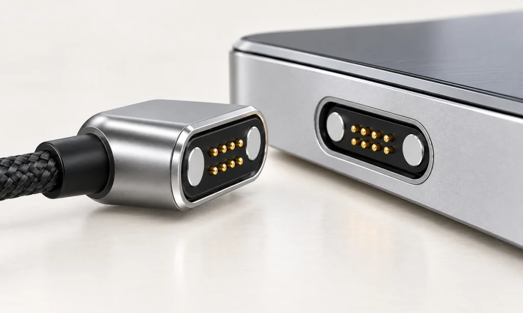
A device may require charging only, charging plus data, identification, control, sensor signals or another custom function. A 4-, 5- or 6-pin connector's function therefore depends on its contact assignments and wiring; the count alone does not establish data capability.
The Complete Transmission Path
A typical physical path is shown below. Data transfer also requires a capable host and device; a power source alone need not provide data.
Host or power source → USB-A / USB-C → cable → magnetic connector → pogo pins → device contact pads → PCB → device electronics.
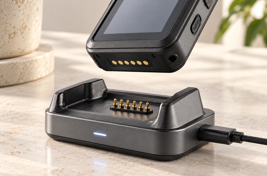
During mating, magnets guide the surfaces into position and the pins compress against their pads. Contacts can be assigned to power and ground or to data, identification and control as the device requires.
Review the PCB, pads, pins, cable terminations, conductors, cable length and opposite-end connector as one electrical path. For OEM development, the magnetic head, cable and PCB need a coordinated evaluation.
Contact Count and Signal Allocation
There is no universal contact count for magnetic data interfaces. Start with the electrical functions that need paths across the connection.
| Contact Count | Possible Design Allocation |
|---|---|
| 2 pins | Power and ground; commonly a charging interface |
| 3 pins | Power, ground and an ID, detection or signal path |
| 4 pins | Power, ground and two signal paths |
| 5 pins | Power/data with an additional ID, detection or control path |
| 6 pins | Several power, data, ID or control paths |
| Multiple pins | A more complex distribution of power and signals |
Scroll horizontally to view every column.
Contact count does not specify a protocol. Pin assignments must work with the complete channel and device electronics. One four-contact design might use VBUS, GND, D+ and D−; another might use V+, GND, ID and Detection. Begin with the schematic and functions before selecting the count.
Designing for USB Data
A magnetic interface can carry USB data when the complete electrical design meets the required functions and characteristics. A USB 2.0-style example may assign four contacts to VBUS, GND, D+ and D−.
USB 2.0| Contact | Possible Function |
|---|---|
| Pin 1 | VBUS |
| Pin 2 | GND |
| Pin 3 | D+ |
| Pin 4 | D− |
Scroll horizontally to view every column.
That assignment does not make every four-contact product USB-compatible. The cable conductors, PCB, device electronics, electrical characteristics and complete signal path must all support the intended communication.
4-pin magnetic connector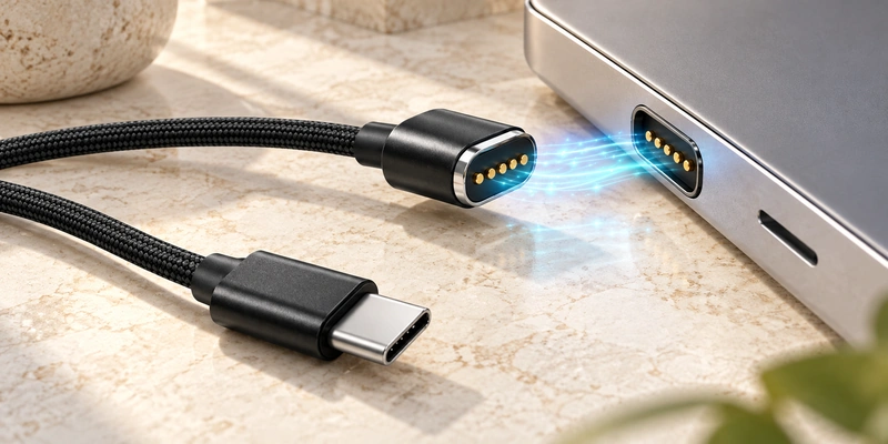
A USB-C plug identifies the physical end interface, not the magnetic cable's actual speed. The magnetic portion may be intended for charging only, USB 2.0 data, identification or another custom function. Confirm the protocol and required data rate separately from the end-connector type.
Factors Affecting Data Performance
Data performance depends on pin assignment, contact resistance, working stroke, contact pressure, cable construction, PCB routing, grounding, shielding, signal return paths and mechanical alignment.

At higher signal rates, review impedance, reflections, insertion loss, crosstalk, cable length and transitions. Poor alignment or insufficient compression can also create intermittent contact and unstable signals.
Assess the OEM interface as a complete assembly:
PCB + device contact + magnetic connector + cable + termination.
The visible pin count is only one part of that assessment.
Requirements for Higher-Speed Signals
A magnetic system can be engineered for higher-speed signals, but its achievable rate depends on the whole channel. Impedance control, contact geometry, grounding, cable construction, shielding, PCB transitions and channel loss become important design requirements.
Do not infer 'high-speed USB' from four contacts or '10 Gb/s' from a USB-C magnetic plug. Define the protocol and rate, design the connector, PCB, cable and signal paths for them, then validate the actual assembly.
Selecting a Power-and-Data Interface
First define voltage, continuous and peak current, communication signals, required data rate and any identification, detection or control paths that need additional contacts.
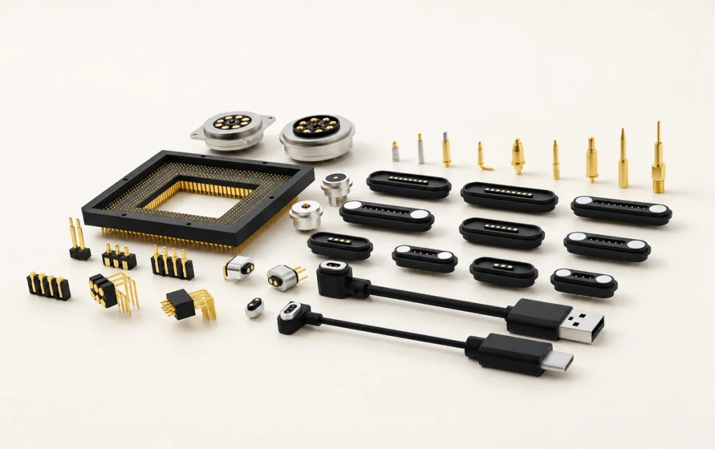
Next specify contact count and pitch, installation space, mating direction, magnetic force, working stroke and cable exit. Confirm the end type—USB-A, USB-C, bare wire or terminals—plus cable length, conductor size and shielding. Review sealing, vibration, repeated mating, sweat and corrosion as environmental requirements.
Magtor can configure assemblies around pin assignment, cable length, wire specification, USB-A / USB-C / bare-wire ends, magnetic structure and the device-side counterpart. Before prototyping, provide the schematic, voltage, current, signal definitions, installation space, end requirement and environment to assess charging-only or combined power-and-data designs.
MagtorDesigning and Validating the Complete Channel
Magnetic connectors can carry data when their electrical design supports it. Magnets supply alignment and retention, while touching conductive contacts form the actual power and signal paths.
Four-, five-, six- and multipin interfaces can allocate functions to suit the device. More complex or higher-speed communication needs coordinated design and validation of the PCB, connector, cable, grounding, shielding and complete signal path.
Define what the device must transmit, then select the contact count, structure, cable and pin assignments around those requirements.
Frequently Asked Questions
1. Can the same magnetic interface carry power and data?
Yes, when the pin assignment, cable wiring and device electronics support both. Separate conductive paths can carry power and signals in that design; the magnets align and retain the connection.
2. What contact count is needed for data?
It depends on the circuit. Four contacts could carry power, ground and two data signals, while five or six can provide extra ID, control or other device-specific paths. These are possible allocations, rather than a universal pin-count rule.
3. Can a four-contact magnetic connector carry USB signals?
It can when the assignments and complete design support the required USB signals. VBUS, GND, D+ and D− form one USB 2.0-style example. Four contacts alone cannot establish USB compatibility.
4. Does a USB-C magnetic cable necessarily transfer data?
No. Its USB-C end does not establish a specific data capability. The cable may be designed for charging only, USB signals, identification or another custom function.
5. Can a magnetic interface be designed for higher speeds?
Yes, subject to the complete channel design. Contact geometry, impedance, grounding, PCB routing, cable construction, shielding and signal integrity need assessment against a defined rate, followed by validation during development.